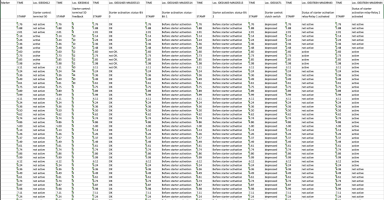
Deeper dive into these fault codes

After checking some wire diagrams looks like the high current relay is in the starter itself and starter relays 1 and 2 in the ebox just provide feed for the starter solenoid but not the cranking power.

If I read diagrams right starter relays are driven by ECU in the ebox, and relay 2 (J907) output has an extra wire that goes to the ECU, BCM and voltage stabiliser. The symbol within relay looks kind of like a potentiometer but without control arm linked - I think this is the measurement wire.

Terminal 1 - GND
Terminal 2 - ECU
Terminal 5 - Starter solenoid
Terminal 3 - Starter relay 1
Terminal 6 - ECU, BCM and voltage stabilizer

View attachment 215495

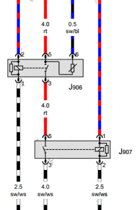
Hmmm... for CAAC engine built before June 2018 I think the circuit is slightly different (wiring diagram No. 6/16)
1696172599582.png

The starter relay 2 (J907) does not have the extra wire to the ECU, etc.
Also black/white wires (from bottom) to the circuitry are from ignition switch terminal 15, thus +12V ignition on.

Would @mmi have any insight into this?
Just got curious about... :thumbsup:

Do I need to do a blockmap capture
Might be helpful - could you please make a couple of full blockmap captures
VCDS > Applications > Controller Channel Map
[Single Controller Address - 01]​
[Measuring Values]​
[CSV file]​
The result file blockmap-01-... will be in folder C:\Ross-Tech\VCDS\Logs\...​
1) ignition ON (engine not running)
2) engine running
3) engine stopped by Stop/Start

Curious what's available for this engine AND possibly even capture something to speculate about the bits vs. engine status (not started/running/stopped)
 
What I can do though is to log the same

Take 1 - the ones I listed in post #15

1696174552019.png

Take 2 - Interestingly I don't have IDE00414. But here's IDE00412, IDE00416 and some bonuses. Different engine versions have little bit different measuring values too :(

1696175645071.png
 

Attachments

  • 2023-10-01-n10n-starter-take1.csv
    4.1 KB · Views: 3
  • 2023-10-01-n10n-starter-take2.csv
    15.6 KB · Views: 2
Hi @mmi Yes I will do that. Thank you for being interested :)

Hi @n10n - thanks very much for doing that. I wonder why I have different data types - bit values rather than words like you. Have I got an older BCM or similar? My VCDS is bang up to date.

I think I've just had a brainwave - I was just watching this video:


And the guy is looking at exactly the same same data items - around terminal 50 as you are both suggesting. This made me think that maybe the 'release conditions' and 'shut-off conditions' might instead refer to the start/stop system i.e.
  • Shut off conditions: Vehicle stationary, clutch not depressed, neutral engaged, battery OK, fuel level high enough etc.
  • Release conditions: clutch depressed etc
If all the shut-off conditions are low, and at least some release conditions are high, this might point to reluctance on auto engine start, but it might be the opposite - reluctance to engage the stop. Does that makes sense or am I talking nonsense?

Code:
Starter control: release conditions-Bits 0-7: 2
                    Starter control: release conditions-Bits 0-7: 86
                    Starter control: shut-off conditions 1-Bits 0-7: 0
                    Starter control: shut-off conditions 1-Bits 0-7: 0

Come to mention it, I do get a 'start/stop not possible' message in the MFD under certain conditions, but I assumed that was insufficiently warm engine or something similar. It then rectifies and S/S always comes back. It's more noticeable in Winter. If I have the AC on to dry the air in winter, I can guarantee that message will appear until the engine is warm.

If that's the case, then this is going to get more complicated and involve data logging while driving - eeek.
 
  • Like
Reactions: mmi
I wonder why I have different data types - bit values rather than words like you. Have I got an older BCM or similar?
Yes, EU5 engines have different ECU (made by Bosch) than EU6 engines (AdbLue) (made by Delphi) - so obviously there are quite a lot of differences in the data itself.

Come to mention it, I do get a 'start/stop not possible' message in the MFD under certain conditions, but I assumed that was insufficiently warm engine or something similar. It then rectifies and S/S always comes back.
You could try to keep cabin air blower at speed 2 or higher to see if that does the trick. With Climatic AC it seems to disable "smart-charging" and and keep battery fully charged which then enables Stop/start more actively. Works at least on EU6 engines :speechless:

Hi @mmi Yes I will do that. Thank you for being interested :)
Of course - whenever VCDS data is mentioned - I'm in ;)
 
I wonder why I have different data types - bit values rather than words like you. Have I got an older BCM or similar? My VCDS is bang up to date.
I wondered about this too - my VCDS is up to date as well. Probably it’s just how the interpretation database for the particular ECU hardware and software version is composed in VCDS.

I think VCDS developers, in US, don’t have access to all engine and software versions at all times. I don’t know where they pull their data from but it’s likely the differences come from databases being developed at different times by different persons.

If all the shut-off conditions are low, and at least some release conditions are high, this might point to reluctance on auto engine start, but it might be the opposite - reluctance to engage the stop. Does that makes sense or am I talking nonsense?

Could be. The truth is that there’s a lot we don’t know without access to the design documentation - we can only make guesses, some more educated (@mmi ;)) and some little bit less.

Come to mention it, I do get a 'start/stop not possible' message in the MFD under certain conditions, but I assumed that was insufficiently warm engine or something similar. It then rectifies and S/S always comes back. It's more noticeable in Winter. If I have the AC on to dry the air in winter, I can guarantee that message will appear until the engine is warm.

S/S has many conditions that prevent it from operating. In winter, electricity consumption is much higher due to all the heating so that alone often prevents S/S, van has to try to make sure it can start again. But even things like cabin not up to specified temp might do it as heat production stops when engine stops.
 
Hmmm... for CAAC engine built before June 2018 I think the circuit is slightly different (wiring diagram No. 6/16)

The starter relay 2 (J907) does not have the extra wire to the ECU, etc.

Hah yes, seems they have flipped the order of relays in some engine versions. The similar wire is in J906 (still called starter relay 1 even if it's closer to starter). I guess from diagnostics perspective much doesn't change - both of the relays have to be in contact anyway for the measurement to work.

Also black/white wires (from bottom) to the circuitry are from ignition switch terminal 15, thus +12V ignition on.

I stand corrected :)
 
Thank you both. I’m now going to have a read up on T5.1 S/S since I might be missing something only looking at T6.
 
Now I’ve got VCDS I can disable S/S for a few days and see if that fault count increases.
 
I've got a date with a stalk-based CCS coming up soon which means accessing the T10 connector under the battery.

Thanks to you both I now understand the connections to the ECU, which looks like in the case of J907, it's just the coil side that's measured, but not the output, whereas 906 has the output measured too. I've got the wiring diagram from the VIP area.

While I'm there, I'll:
  • Replace relays J906/7 which are 507 / 645s.
  • Visually inspect the connections and check continuity to the ECU, which is pin 1 of relay 2 to the ECU, and pins 2&6 of relay 1 to the ECU
  • I'll have the dash apart anyway to feed the T10 connection, so I'll check fuse SC23, although it's hard to see how it would start at all if that fuse had blown.
I found these two cases on the ross-tech website. The first is almost identical - only that the fault actually escalated to EML, which mine hasn't, but that's a CFCA engine so it might have a different ECU, and different criteria for elevation.


The second is extremely similar too

Annoyingly, both trails go cold, which appears to be a common feature of the Ross-Tech forum.
 
Thanks to you both I now understand the connections to the ECU, which looks like in the case of J907, it's just the coil side that's measured, but not the output, whereas 906 has the output measured too

That is correct but I would like to think 906 output measument really measures both 906 and 907 - both relays have to conduct for the starter to crank and thats when the voltage at output pin of 906 is of interest. Inversely, if either one of the relays is borken, voltage stays low.

While I'm there, I'll:
  • Replace relays J906/7 which are 507 / 645s.
  • Visually inspect the connections and check continuity to the ECU, which is pin 1 of relay 2 to the ECU, and pins 2&6 of relay 1 to the ECU
  • I'll have the dash apart anyway to feed the T10 connection, so I'll check fuse SC23, although it's hard to see how it would start at all if that fuse had blown.

Sounds like a plan! :thumbsup:


Annoyingly, both trails go cold, which appears to be a common feature of the Ross-Tech forum.

All too common, I agree. I believe many bite the bullet and shell out to dealers pocket in the end. Or just don’t bother updating as also quite often there’s no tangible direct helpful advice from the forums.
 
both relays have to conduct for the starter to crank and thats when the voltage at output pin of 906 is of interest
That makes sense - thank you for explaining.
 
that's a CFCA engine so it might have a different ECU,
It's the same ECU as with CAAC engine. Also the starter relay circuitry is identical.


Have you kept eye when the fault codes appear?

A kind of interesting case would be to check the codes just after ignition is turned on - before cranking engine.
If that would be the case - would that indicate the source would be internal to ECU?
 
It's the same ECU as with CAAC engine. Also the starter relay circuitry is identical.
That's very interesting then. At least one other confirmed case with the same engine and ECU. In that one, the engineer tried everything that I'm due to try to no avail.
A kind of interesting case would be to check the codes just after ignition is turned on - before cranking engine.
I suspect it does happen before cranking. I cleared all codes the other day then ran a scan just with ignition but not cranked, and it was there straight away an accurate date an time of the scan. That's the autoscan that I posted in post #8.

Is there a way to capture data where VCDS logs all Module 01 events in chronological order? In the same way that debug events are presented in software development? The blockmap seems very helpful but as I understand it, it's presented in numerical order and captured by polling across all channels cyclically.

The advanced measurement is OK but that seems designed to look at specific data points at synchronised time intervals.

I'm beginning to like VCDS and forgive its clunky interface.
 
A kind of interesting case would be to check the codes just after ignition is turned on - before cranking engine.
If that would be the case - would that indicate the source would be internal to ECU?
Interesting line of thought!

I guess theoretically ECU could ”microburst” (low current quick pulse) relays individually before cranking in order to measure coils without really cranking. The failure (ECU internal or external) of such test could read as ”control circuit short to ground”. But then the other fault specifically mentioned output :unsure:

Also energizing relays, even with limited energy, would be kind of playing with the fire - two relays are obviously a safety setup. If one of the relays fails so that it conducts always the other relay saves the day. It would be bad if the engine cranked unexpectedly while a tech had their hands on belts.
 
Is there a way to capture data where VCDS logs all Module 01 events in chronological order? In the same way that debug events are presented in software development?
Unfortunately no. This would be the holy grail but there is no such interface, at least not a public one. Maybe through jtag headers on circuit board or through some black magic bench testing commands executed through CAN… but these would be strictly limited to factory diagnostics.

I’m deep in the rabbit hole investigating internal CAN traffic beyond what can be seen through diagnostic port but even there, mostly *outcomes* of various modules are present, not that much individual pin or sensor values.
 
I guess it could just be an internal ECU error.
 
Unfortunately no. This would be the holy grail but there is no such interface, at least not a public one. Maybe through jtag headers on circuit board or through some black magic bench testing commands executed through CAN… but these would be strictly limited to factory diagnostics.

I’m deep in the rabbit hole investigating internal CAN traffic beyond what can be seen through diagnostic port but even there, mostly *outcomes* of various modules are present, not that much individual pin or sensor values.
That’s a shame. Very interesting topic though.
 
I suspect it does happen before cranking. I cleared all codes the other day then ran a scan just with ignition but not cranked, and it was there straight away an accurate date an time of the scan. That's the autoscan that I posted in post #8.
Interesting... could it be self-diagnostics at ECU start-up?
What about clearing the fault then before cranking - does it stay clear?
What about after engine is started? Etc.

The fault in the autoscan was "Not confirmed" thus it was not present anymore at the moment of the autoscan.
 
OK, I think we're getting a little bit closer with this test. Here are two sequences that result in four scans:

IGN on, clear, scanA1, IGN off, key out, IGN on, scanA2

later...

IGN on, clear, scanA3, crank, scanA4, engine off

A1: 01-Engine -- Status: OK 0000
A2: 01-Engine -- Status: Malfunction 0010
A3: 01-Engine -- Status: OK 0000
A4: 01-Engine -- Status: OK 0000

So I'm pretty confident that those test prove that it's the initiation of the system (IGN on) where the fault is present, and cranking has nothing to do with it. This marries with observed reality - it starts every time.

That leaves me thinking that it's either an ECU initialisation routine that is going wrong somehow, or maybe leading us back to what we all have suspected at one point or another, that there's a foreign device in the starter circuit somewhere that saps power when the IGN is first switched on, but then becomes invisible once it has powered-up properly. Could be a tracker or immobiliser box somewhere in the dash, which is the only place I haven't looked.

This guy had a very similar issue...


...and there is mention of something similar on this forum that was referred-to in post #1.

Thoughts invited!
 
Back
Top