You are using an out of date browser. It may not display this or other websites correctly.
You should upgrade or use an alternative browser.
You should upgrade or use an alternative browser.
[Guide] Mobile Solar Panels ? . . . - How I Did It -
- Thread starter Dellmassive
- Start date
Today's test:
BlueFusion 120W kit
a continuation of : Mobile Solar Panels ? . . . - How I Did It -
But this time on the Van.
Its a folded panel like the 50W version,

checking the spec we have:
so 6.67A max (Imp) (7.20A ISC Max) - so thats enough under the 10A i like to use for a 12V socket.

next job to swap out the supplied crock-clamps for a 12v socket lead.
"heres one i prepared earlier" - lol.
its a 16AWG 5mtr 12v plug/socket extension lead.
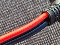
i cut it down to about 4mtrs and checked it was fused . . .

then just swapped over the screw terminals, (keeping the other lead for another day)

Next it was out to the van, its too big for the dash so i popped it on the roof long ways . . .

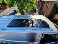
and fixed in place with a couple of strong magnets . . .

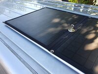
cable run . .

plugged into the starter battery socket . . . .

which brought the unit into life . . .

*********************************************************
weather wise we are looking good for today:

from the pics you can see the tree shading and the building that shades the van and panel in that location.
the current battery states are @ 800hrs :
starter battery:


and remembering the DC-DC charger (Currently Redarc) will "Auto VSR" when the starter is up to 13v and start charging the Aux battery
here is the Aux battery :


TBC later . . . . . . . .
1315hrs and something is not right.
for 120W i should be smashing it . . . . but the readings are very low, below 13v still... (no auto VSR yet?)

i checked with a amp meter and had a jumping reading from 3A to 0.6A . . . something not right here.


to test things i swapped out the controller for a Victron 75/15.. . . . . then BOOM !
TBC . . . . PIC LIMIT . . . .
BlueFusion 120W kit
a continuation of : Mobile Solar Panels ? . . . - How I Did It -
But this time on the Van.
Its a folded panel like the 50W version,

checking the spec we have:
so 6.67A max (Imp) (7.20A ISC Max) - so thats enough under the 10A i like to use for a 12V socket.

next job to swap out the supplied crock-clamps for a 12v socket lead.
"heres one i prepared earlier" - lol.
its a 16AWG 5mtr 12v plug/socket extension lead.

i cut it down to about 4mtrs and checked it was fused . . .

then just swapped over the screw terminals, (keeping the other lead for another day)

Next it was out to the van, its too big for the dash so i popped it on the roof long ways . . .


and fixed in place with a couple of strong magnets . . .


cable run . .

plugged into the starter battery socket . . . .

which brought the unit into life . . .

*********************************************************
weather wise we are looking good for today:

from the pics you can see the tree shading and the building that shades the van and panel in that location.
the current battery states are @ 800hrs :
starter battery:


and remembering the DC-DC charger (Currently Redarc) will "Auto VSR" when the starter is up to 13v and start charging the Aux battery
here is the Aux battery :


TBC later . . . . . . . .
1315hrs and something is not right.
for 120W i should be smashing it . . . . but the readings are very low, below 13v still... (no auto VSR yet?)

i checked with a amp meter and had a jumping reading from 3A to 0.6A . . . something not right here.


to test things i swapped out the controller for a Victron 75/15.. . . . . then BOOM !
TBC . . . . PIC LIMIT . . . .
Last edited:
Test number 3 completed today.
This was with the Bluefusion 50W panel connected directly the the CTEK250SE installed in my van, not using the controller that was supplied with the solar panels.
To start with I had to make up some cables as follows:
This enables me to connect the original controller to the panels or to disconnect the original controller and connect via the extension cable to the CTEK, thus giving me the flexibility to connect to other stuff if i need to (e.g. direct to the Starter battery or to one of my motorcycle batteries).
- I cut the cable between the solar panel and the solar controller supplied with it and inserted a pair of powerpole connectors on each of the cut ends
- I made a new extension cable from 14AWG red/black and terminated each end in a pair of powerpole connectors
- I made a short cable from 14AWG cable terminated in a pair of powerpole connectors on one end and M8 eyelets on the other. This connects to the CTEK
The cables look like this:
View attachment 71894
Connected to the original controller:
View attachment 71895
Bypassing the original controller:
View attachment 71896
And the short connector added to the CTEK: I then just poked the connector through so it is easily accessible from under the front of the drivers seat.
View attachment 71897
So with the cabling made up I started the test in the same way as the previous two.
I connected the panel a little before 7AM this morning and laid it on the roof. At this time there is no sun on the van.
BM2 reading from before connecting up:
View attachment 71898
The sun gets on to the van around 9.30AM. You will see in the trace below that there was a very small charge up until around 9.30 and from then it increased significantly and continued to climb pretty much all day. This looks much less peaky than the two previous tests. I moved the panel onto the front of the van up against the windscreen but I can’t remember exactly when. I think it was where the slight dip is at 14:30ish. It was obviously catching more light from then on as the graph gets a little steeper.
Unfortunately I had to go out in the van at 3PM hence the test ending then. I’d have like to have got to the point where the CTEK started to trickle charge the starter battery but I didn’t get that far.
View attachment 71899
At 3PM I took my dog for a walk on the beach (I live very close). While I was there I thought I’d stick the panel on again but this time inside the windscreen. Later in the day, laid flatter and behind the glass so probably not the optimal setup but worth a go and a rel life situation. This is the trace extended to include that period. The two high peaks are the drive there and the drive back, the flat section where it is around 13.5V is the period the panel was connected up in this way:
View attachment 71901
As I said, I’d like to have got to the point where the CTEK started to trickle charge the starter battery but other than that I am very pleased with the results.
I set out to test whether a cheapish portable solar panel would be capable of charging starter or leisure batteries for periods where the van is not in use or whilst remote and parked up. I’m happy that it will do this given decent sunshine. What I have learned is that the CTEK appears to be the better way of charging the leisure battery. I’d like to test the reverse charge of the starter battery but will need to find a suitable window where I can leave the van for longer to do this. A higher output panel would obviously do this more quickly but i think for my personal needs what I have works.
side thread: . . . . . . . . . . (@Big.mac )
i just noticed something on your D250SE pic . . . . the ground cable looks a bit thin?

book says 12AWG or 4mm"2 or thicker? (but can tell what size it is from the pic? but it looks too small/thin?)

not sure from the pic but it looks like it goes to the bolt at the bottom of the pic? on yellow crimps?
might be worth fitting a nice beefy fat cable to replace the thin one?
on DC-DC units i normally fit the same Gauge cable as the positive battery feeds.
Remember current flows through that ground terminal as well as the battery in/out.
Thanks @Dellmassive. I too noticed the same thing when i connected up the solar cable. I didn’t fit the CTEK myself so I had already added this to my list of things to do. I’m equally not sure why it is on a separate earth point to the battery. You can just make out the battery earth point just at the top of the CTEK. I would have connected them both to the same point. I just need to get a short bit of suitable gauge cable and crips to match.side thread: . . . . . . . . . . (@Big.mac )
i just noticed something on your D250SE pic . . . . the ground cable looks a bit thin?
View attachment 72167
book says 12AWG or 4mm"2 or thicker? (but can tell what size it is from the pic? but it looks too small/thin?)
View attachment 72164
not sure from the pic but it looks like it goes to the bolt at the bottom of the pic? on yellow crimps?
might be worth fitting a nice beefy fat cable to replace the thin one?
on DC-DC units i normally fit the same Gauge cable as the positive battery feeds.
Remember current flows through that ground terminal as well as the battery in/out.
Today's test:
BlueFusion 120W kit
a continuation of : Mobile Solar Panels ? . . . - How I Did It -
But this time on the Van.
Its a folded panel like the 50W version,
View attachment 72146
checking the spec we have:
so 6.67A max (Imp) (7.20A ISC Max) - so thats enough under the 10A i like to use for a 12V socket.
View attachment 72147
next job to swap out the supplied crock-clamps for a 12v socket lead.
"heres one i prepared earlier" - lol.
its a 16AWG 5mtr 12v plug/socket extension lead.
View attachment 72148
i cut it down to about 4mtrs and checked it was fused . . .
View attachment 72149
then just swapped over the screw terminals, (keeping the other lead for another day)
View attachment 72150
Next it was out to the van, its too big for the dash so i popped it on the roof long ways . . .
View attachment 72151View attachment 72157
and fixed in place with a couple of strong magnets . . .
View attachment 72152View attachment 72153
cable run . .
View attachment 72154
plugged into the starter battery socket . . . .
View attachment 72155
which brought the unit into life . . .
View attachment 72156
*********************************************************
weather wise we are looking good for today:
View attachment 72158
from the pics you can see the tree shading and the building that shades the van and panel in that location.
the current battery states are @ 800hrs :
starter battery:
View attachment 72159View attachment 72160
and remembering the DC-DC charger (Currently Redarc) will "Auto VSR" when the starter is up to 13v and start charging the Aux battery
here is the Aux battery :
View attachment 72161View attachment 72162
TBC later . . . . . . . .
1315hrs and something is not right.
for 120W i should be smashing it . . . . but the readings are very low, below 13v still... (no auto VSR yet?)
View attachment 72188
i checked with a amp meter and had a jumping reading from 3A to 0.6A . . . something not right here.
View attachment 72190View attachment 72191
to test things i swapped out the controller for a Victron 75/15.. . . . . then BOOM !
TBC . . . . PIC LIMIT . . . .
continued from above: . . . . .
to test things i swapped out the controller for a Victron 75/15. MPPT . . . . . then BOOM !

straight up to 13v . . . . so we know the panel is good.

the BM2 shows an immediate rise in voltage . .

and the victron shows the stats . .


So the panels good.
whats the issues here? . . . the controller? . . . or just PWM in general?
so next i swapped out the PMW for the other PWM i had on the 50W kit . . .
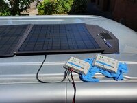
i got the same result . . . . . 12.8v . . . but not above the 13v i was looking for . . .

ok so it must be something to do with the controller throttling the power from the panel . . . .
so next was to try a different PWM controller . . . . this time the new Renogy PWM . . .

wired in . . .
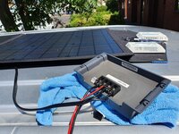
then BOOM again !!!
4.9A going to battery and voltage rising again.. . . . . !!
The Renogy PWM has been on for 5mins. . . . . just look at the readings !!!!!!
14.4V . . . . .boosting the starter !
above 13v so the DC-DC has kicked in
and now charging the Aux battery too.


*********************
Renogy Wanderer Li 30A 12V PWM Negative Ground Charge Controller Compatible with Lithium, Sealed, Gel, and Flooded batteries and Renogy Bluetooth Module: Amazon.co.uk: Garden & Outdoors
Shop Renogy Wanderer Li 30A 12V PWM Negative Ground Charge Controller Compatible with Lithium, Sealed, Gel, and Flooded batteries and Renogy Bluetooth Module. Free delivery on eligible orders of £20 or more.
amzn.to
Renogy Voyager - 20A Negative PWM Waterproof Charge Controller w/LCD Display and LED Bar

.
so we know that the included solar PWM controller is a cheapy for the price of the kit . . . . . but it seems that above 50W it just doesn't cut it.
here I've shown two examples of the very same panel giving twice to three times the through put as the LS1024EU.
first example was the Victron 75/15 MPPT.
second was the Renogy 20A PWM.
Moral of the story is : - Any Solar panels performance will be increased with a decent solar controller.
and,
you get what you pay for, so a cheap kit = cheap controller.
the good thing is its easy to swap out the controller. =]
.
Test ended @ 2030hrs due to getting the van ready for work . . .
The 120w panel was left connected to the Renogy for the remainder of the day . . .
you can see the Renogy done a stellar job Boosting the battery from around 1445hrs
then dropped to float @ 1645hrs
and still holding 13v untill 1900hrs.

starter battery @ 2017hrs :

lets look at the AUX battery . . . . we are expecting it to be charged via the Redarc Auto VSR DC-DC when the starter battery reaches 13v and over.
as expected the AUX started charging at 1315hrs (The Victron 75/15 was connected at that point)
and was kept at float all the way untill 200hrs ish. (Renogy PWM)

the AUX battery final voltage @ 12.61v

and so you can see the results together here is the BM3 readout . . .
you can clearly see that the supplied PWM controller was keeping the starter at around 12.8v, which was not high enough for the Redarc DC-DC to kick in. . .
as soon as we swapped over the controller, Victron, then Renogy you can see the panel coming into life and charging bothe batterys with at least 5A charge current as witnessed on the Victron App.


Conclusion . . .
The Panel is great and will deliver the power down to low light levels with a decent controller.
The supplied controller is not so great at getting the most out of the panels at varing conditions.
even though the controller spec states 14.4v boost, 13.8v float
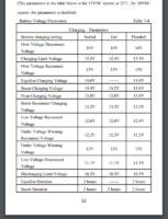
im still unsure why the LS1024EU performed so badly on this occasion. . . . . and as we see from the results above the Victron & Renogy controllers well out performed it using the same panel, same van, same cables, same battery, same everything.
Possible faulty unit i though, which is why i swapped them over . . .?
but the second LS1024EU gave similar results.
in the end swapping the controller out for a known good worked great. . . .
remember this is for the 120W panel . . . . so maybe the higher amps was causing a problem?
***********************
For now i think i will leave the Renogy PWM connected to the panel.

Last edited:
The "-"-terminal on the CTEK D250SE is just the ground "reference", so no significant current going through that one (just reference+small current to drive the electronics). All the "powerful" things are happening between "+"-terminals and all the the energy sources and sinks share common ground at chassis.i just noticed something on your D250SE pic . . . . the ground cable looks a bit thin?
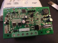
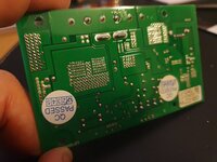
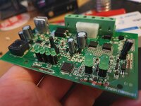
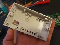
For anyone thats interested i thought i would have a look inside the EPEVER LS1024EU . . . .continued from above: . . . . .
to test things i swapped out the controller for a Victron 75/15. MPPT . . . . . then BOOM !
View attachment 72198
straight up to 13v . . . . so we know the panel is good.
View attachment 72193
the BM2 shows an immediate rise in voltage . .
View attachment 72195
and the victron shows the stats . .
View attachment 72196View attachment 72197
So the panels good.
whats the issues here? . . . the controller? . . . or just PWM in general?
so next i swapped out the PMW for the other PWM i had on the 50W kit . . .
View attachment 72199
i got the same result . . . . . 12.8v . . . but not above the 13v i was looking for . . .
View attachment 72200
ok so it must be something to do with the controller throttling the power from the panel . . . .
so next was to try a different PWM controller . . . . this time the new Renogy PWM . . .
View attachment 72201
wired in . . .
View attachment 72202
then BOOM again !!!
4.9A going to battery and voltage rising again.. . . . . !!
The Renogy PWM has been on for 5mins. . . . . just look at the readings !!!!!!
14.4V . . . . .boosting the starter !
above 13v so the DC-DC has kicked in
and now charging the Aux battery too.
View attachment 72203
View attachment 72204
*********************
Renogy Wanderer Li 30A 12V PWM Negative Ground Charge Controller Compatible with Lithium, Sealed, Gel, and Flooded batteries and Renogy Bluetooth Module: Amazon.co.uk: Garden & Outdoors
Shop Renogy Wanderer Li 30A 12V PWM Negative Ground Charge Controller Compatible with Lithium, Sealed, Gel, and Flooded batteries and Renogy Bluetooth Module. Free delivery on eligible orders of £20 or more.amzn.to
Renogy Voyager - 20A Negative PWM Waterproof Charge Controller w/LCD Display and LED Bar
View attachment 72206
.
so we know that the included solar PWM controller is a cheapy for the price of the kit . . . . . but it seems that above 50W it just doesn't cut it.
here I've shown two examples of the very same panel giving twice to three times the through put as the LS1024EU.
first example was the Victron 75/15 MPPT.
second was the Renogy 20A PWM.
Moral of the story is : - Any Solar panels performance will be increased with a decent solar controller.
and,
you get what you pay for, so a cheap kit = cheap controller.
the good thing is its easy to swap out the controller. =]
.
Test ended @ 2030hrs due to getting the van ready for work . . .
The 120w panel was left connected to the Renogy for the remainder of the day . . .
you can see the Renogy done a stellar job Boosting the battery from around 1445hrs
then dropped to float @ 1645hrs
and still holding 13v untill 1900hrs.
View attachment 72244
starter battery @ 2017hrs :
View attachment 72245
lets look at the AUX battery . . . . we are expecting it to be charged via the Redarc Auto VSR DC-DC when the starter battery reaches 13v and over.
as expected the AUX started charging at 1315hrs (The Victron 75/15 was connected at that point)
and was kept at float all the way untill 200hrs ish. (Renogy PWM)
View attachment 72246
the AUX battery final voltage @ 12.61v
View attachment 72247
and so you can see the results together here is the BM3 readout . . .
you can clearly see that the supplied PWM controller was keeping the starter at around 12.8v, which was not high enough for the Redarc DC-DC to kick in. . .
as soon as we swapped over the controller, Victron, then Renogy you can see the panel coming into life and charging bothe batterys with at least 5A charge current as witnessed on the Victron App.
View attachment 72248View attachment 72249
Conclusion . . .
The Panel is great and will deliver the power down to low light levels with a decent controller.
The supplied controller is not so great at getting the most out of the panels at varing conditions.
even though the controller spec states 14.4v boost, 13.8v float
View attachment 72253
im still unsure why the LS1024EU performed so badly on this occasion. . . . . and as we see from the results above the Victron & Renogy controllers well out performed it using the same panel, same van, same cables, same battery, same everything.
Possible faulty unit i though, which is why i swapped them over . . .?
but the second LS1024EU gave similar results.
in the end swapping the controller out for a known good worked great. . . .
remember this is for the 120W panel . . . . so maybe the higher amps was causing a problem?
***********************
For now i think i will leave the Renogy PWM connected to the panel.
View attachment 72252
i gotta say its rather nice inside . . . . .
con-formally coated PCB,
very nice tracks and veers for current flow.
internal fuse,
mosfets, IC and a Ferite core . . . .
compared to some cheap PWM I've seen this one ticks all the boxes . . . .
which is even more strange as to my it performed badly . . .
****




*****
following on from the BlueFusion 120W saga and included solar controller . . . .continued from above: . . . . .
to test things i swapped out the controller for a Victron 75/15. MPPT . . . . . then BOOM !
View attachment 72198
straight up to 13v . . . . so we know the panel is good.
View attachment 72193
the BM2 shows an immediate rise in voltage . .
View attachment 72195
and the victron shows the stats . .
View attachment 72196View attachment 72197
So the panels good.
whats the issues here? . . . the controller? . . . or just PWM in general?
so next i swapped out the PMW for the other PWM i had on the 50W kit . . .
View attachment 72199
i got the same result . . . . . 12.8v . . . but not above the 13v i was looking for . . .
View attachment 72200
ok so it must be something to do with the controller throttling the power from the panel . . . .
so next was to try a different PWM controller . . . . this time the new Renogy PWM . . .
View attachment 72201
wired in . . .
View attachment 72202
then BOOM again !!!
4.9A going to battery and voltage rising again.. . . . . !!
The Renogy PWM has been on for 5mins. . . . . just look at the readings !!!!!!
14.4V . . . . .boosting the starter !
above 13v so the DC-DC has kicked in
and now charging the Aux battery too.
View attachment 72203
View attachment 72204
*********************
Renogy Wanderer Li 30A 12V PWM Negative Ground Charge Controller Compatible with Lithium, Sealed, Gel, and Flooded batteries and Renogy Bluetooth Module: Amazon.co.uk: Garden & Outdoors
Shop Renogy Wanderer Li 30A 12V PWM Negative Ground Charge Controller Compatible with Lithium, Sealed, Gel, and Flooded batteries and Renogy Bluetooth Module. Free delivery on eligible orders of £20 or more.amzn.to
Renogy Voyager - 20A Negative PWM Waterproof Charge Controller w/LCD Display and LED Bar
View attachment 72206
.
so we know that the included solar PWM controller is a cheapy for the price of the kit . . . . . but it seems that above 50W it just doesn't cut it.
here I've shown two examples of the very same panel giving twice to three times the through put as the LS1024EU.
first example was the Victron 75/15 MPPT.
second was the Renogy 20A PWM.
Moral of the story is : - Any Solar panels performance will be increased with a decent solar controller.
and,
you get what you pay for, so a cheap kit = cheap controller.
the good thing is its easy to swap out the controller. =]
.
Test ended @ 2030hrs due to getting the van ready for work . . .
The 120w panel was left connected to the Renogy for the remainder of the day . . .
you can see the Renogy done a stellar job Boosting the battery from around 1445hrs
then dropped to float @ 1645hrs
and still holding 13v untill 1900hrs.
View attachment 72244
starter battery @ 2017hrs :
View attachment 72245
lets look at the AUX battery . . . . we are expecting it to be charged via the Redarc Auto VSR DC-DC when the starter battery reaches 13v and over.
as expected the AUX started charging at 1315hrs (The Victron 75/15 was connected at that point)
and was kept at float all the way untill 200hrs ish. (Renogy PWM)
View attachment 72246
the AUX battery final voltage @ 12.61v
View attachment 72247
and so you can see the results together here is the BM3 readout . . .
you can clearly see that the supplied PWM controller was keeping the starter at around 12.8v, which was not high enough for the Redarc DC-DC to kick in. . .
as soon as we swapped over the controller, Victron, then Renogy you can see the panel coming into life and charging bothe batterys with at least 5A charge current as witnessed on the Victron App.
View attachment 72248View attachment 72249
Conclusion . . .
The Panel is great and will deliver the power down to low light levels with a decent controller.
The supplied controller is not so great at getting the most out of the panels at varing conditions.
even though the controller spec states 14.4v boost, 13.8v float
View attachment 72253
im still unsure why the LS1024EU performed so badly on this occasion. . . . . and as we see from the results above the Victron & Renogy controllers well out performed it using the same panel, same van, same cables, same battery, same everything.
Possible faulty unit i though, which is why i swapped them over . . .?
but the second LS1024EU gave similar results.
in the end swapping the controller out for a known good worked great. . . .
remember this is for the 120W panel . . . . so maybe the higher amps was causing a problem?
***********************
For now i think i will leave the Renogy PWM connected to the panel.
View attachment 72252
Then seeing the inside, i thought i would give it another go.
strictly following the connection requirements.
1- +12v Battery first
2- then solar second . . . (so i kept the panel closed and covered untill after the unit was plugged into the 12v socket)
yesterdays other controllers took the battery straight to 14.4v boost/bulk then 13.8v float . . . . . .
lets see what happens:
start test @ 0850hrs

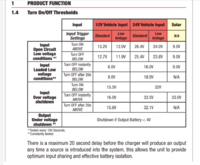
we are looking for the starter battery to rise to 13.2v so the Redarc will kick in "uto VSR" mode and start charging the AUX . . . .
RE: Redarc . . .
.
0929hrs: so far its just keeping the battery at around 13.2v . . . . but the Redarc hasnt kicked in yet . . .

..
here we go . . .
0930hrs: the Redarc has started up after seeing the 13.2v for a while. Giving the AUX battery an initial Bulk charge, then dropping to float. (battery is 100% anyway)
acording to the Redarc chart above . . . it should stay running now untill the starter battery voltage drops to 12.7v . . .

Lets see if the combo can keep the starter battery above 13v . . . . . .
***
just went out the van to take some pics of the charger etc, it looks like opening the doors has started up the vans modules + lights which has dropped the starter battery to below 12.7 and the Redarc has cut out . . . . .
i also changed the profile to FLOODED to see if that would help . . . .

.

.
1011hrs: things seem to have settled down again . . .

to test things i went out the van again . . . as soon as the door opens and the lights and modules power up the starter battery voltage drops off.

under load we were getting about 2.68A to the battery with the clamp meter.
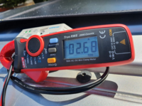
..
so to test again i swapped out the solar controller for the Renogy PWM . . . the battery was @ 12.6v at this point with the door open.

.
right away we had more current flow . . . and the starter voltage started rising. . . .
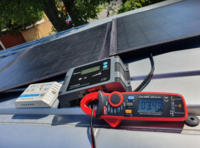
Then BOOM . . . . 14.6v bulk mode =]

.
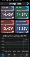
.
You can see the difference right away . . The Renogy has move to 14.6v bulk, the Redarc has kicked in and charging the AUX and the voltage levels are high.
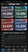
so whats to be made of this? . . . . .
The Renogy & Victron are better controllers hands down . . . . but they are significantly more expensive.
I think the qwerks with the LS1024EU are down to the firmware in regards to the bulk,float, trigger voltages and maps . . .etc. as it seems that the hardware can handle the watts, volts, amps.
so if your happy with the LS1024EU controller then stick with it . . .
But if you want better performance out of your panel then upgrade to a better quality PWM controller . . . The Renogy always seem to perform well.
and ultimately look at getting a MPPT controller to max out your panels potential . . .
Victron is the daddy IMHO and the monitoring APP is the best out there.
many DC-DC chargers now have an MPPT input built in so try that if you have it.
=]
Test End . . .
.......
Last edited:
Continuation of 50W portable panel testing.
The van has not been used for a couple of days so I figured this was the ideal time to test to see if the 50W panel, coupled with the CTEK was good enough to use to keep batteries alive whilst the van is laid up.
Connections are as follows:
I connected it on Sunday evening and have not touched it or the van since then. The only load of any kind that should be active is my dashcam which is connected to the leisure battery and records in ‘parking mode’.
So to the results:
Yesterday the CTEK directed the charging towards the Leisure battery up until about 15:00 when it switched across to the starter battery. The sun goes off the van 5 so at this point the charging drops.
Today, the CTEK continued charging the Starter battery until about 15:00 and then switched to the Leisure battery.
The sun doesn’t get onto the front of the van until about 9 in the morning hence the charging starting from around that time.


For me this is ideal. I know I can repeat what I have done over the last couple of days if I’m leaving the van unused for a few days and the batteries won’t die on me (Either of them). It also confirms I made the right choice in the CTEK250SE which I chose because it allowed connection of a solar panel and would trickle charge the starter battery once the leisure battery is full. If i was going off grid for a while or more heavily loading my leisure circuit I could simply attach a bigger solar panel, perhaps I could borrow one of @Dellmassive’s huge collection of them
I’m going to leave the panel where it is until I need to use the van.
The van has not been used for a couple of days so I figured this was the ideal time to test to see if the 50W panel, coupled with the CTEK was good enough to use to keep batteries alive whilst the van is laid up.
Connections are as follows:
- 50W BlueFusion portable panel connected directly to MPPT controller input on the CTEK 250SE DC-DC charger. (Not using PWM controller supplied with panel)
- Panel placed on dashboard (i.e. inside the van behind the windscreen).
I connected it on Sunday evening and have not touched it or the van since then. The only load of any kind that should be active is my dashcam which is connected to the leisure battery and records in ‘parking mode’.
So to the results:
Yesterday the CTEK directed the charging towards the Leisure battery up until about 15:00 when it switched across to the starter battery. The sun goes off the van 5 so at this point the charging drops.
Today, the CTEK continued charging the Starter battery until about 15:00 and then switched to the Leisure battery.
The sun doesn’t get onto the front of the van until about 9 in the morning hence the charging starting from around that time.


For me this is ideal. I know I can repeat what I have done over the last couple of days if I’m leaving the van unused for a few days and the batteries won’t die on me (Either of them). It also confirms I made the right choice in the CTEK250SE which I chose because it allowed connection of a solar panel and would trickle charge the starter battery once the leisure battery is full. If i was going off grid for a while or more heavily loading my leisure circuit I could simply attach a bigger solar panel, perhaps I could borrow one of @Dellmassive’s huge collection of them
I’m going to leave the panel where it is until I need to use the van.
Good test, nice results.
50w is the min size I recommend for dash top solar charging..
And you welcome to borrow a larger panel any time.
=)
50w is the min size I recommend for dash top solar charging..
And you welcome to borrow a larger panel any time.
=)
I’ve been watching this thread with interest as I’m looking to add mobile solar to my van to allow us to be off grid stationary for longer and 120w BlueFusion panel would appear to be ideal. We are only running a CRX50, LED lights and charging mobile devices and without solar and the current lead acid 95ah battery we are good for 2 days so I’m thinking of somewhere 100w to 150w of solar will cover it.
The only thing putting me off is the disclaimer about having to “protect from substantial rain”. Any thoughts on this? Anybody had their BlueFusion panel out in substantial rain as a result of a sudden shower? is it maybe because of the controller? I was initially planning to use the supplied PWM controller and then upgrade to a Victron MPPT Inside the van. There is quite a big price hike to a similar spec Lensun panel which I was also considering....
The only thing putting me off is the disclaimer about having to “protect from substantial rain”. Any thoughts on this? Anybody had their BlueFusion panel out in substantial rain as a result of a sudden shower? is it maybe because of the controller? I was initially planning to use the supplied PWM controller and then upgrade to a Victron MPPT Inside the van. There is quite a big price hike to a similar spec Lensun panel which I was also considering....
If your worried about rain just go for a semi flexible panel...
Like the lensun I've shown... or similar.
They are basically waterproof.
Though I doubt a bit of rain would do anything to the folding penel I'd use MC4 MC4 conectors to move the controller to a dry location...
Like the lensun I've shown... or similar.
They are basically waterproof.
Though I doubt a bit of rain would do anything to the folding penel I'd use MC4 MC4 conectors to move the controller to a dry location...
Do you guys put a fuse between your solar panel and MPPT? I have fused pretty much every other +ve connection i have on the van, but lots of people say due to how solar works you don't need this and you want as few connections between the panel and the MPPT as possible.... I would have thought it should still have a 20A fuse on the +ve cable, but what are you guys doing? If you are fusing it, what type of fuses have you gone for?
Mine isn’t fused. I looked at the CTEK manual and that didn’t require a fuse so I didn’t use one.Do you guys put a fuse between your solar panel and MPPT? I have fused pretty much every other +ve connection i have on the van, but lots of people say due to how solar works you don't need this and you want as few connections between the panel and the MPPT as possible.... I would have thought it should still have a 20A fuse on the +ve cable, but what are you guys doing? If you are fusing it, what type of fuses have you gone for?
I'm CTEK too, thats what I was seeing, just didn't feel right ha!
panel to controller doesn't need fusing . . . for 50w-150w (ISC 3A-9A)
possibly above 150w if you wanted,
definatly 50V up and/or larger systems of 300W up.
but controller to battery needs fusing at battery.
so no fuse required at ctek solar input.
possibly above 150w if you wanted,
definatly 50V up and/or larger systems of 300W up.
but controller to battery needs fusing at battery.
so no fuse required at ctek solar input.
Nice one Dell. I've got a 30a fuse between the CTEK and the battery but won't for the charger.
Thanks guys, the panel arrives tomorrow
Thanks guys, the panel arrives tomorrow
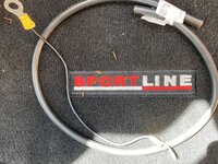
Replaced the ground cable on the CTEK today. While i had the seat out I stuck the clip on ammeter onto the ground cable and it looks to me as if there is current flow through it. Anyways it’s sorted now with a 16mm cable so I won’t need to worry either way.The "-"-terminal on the CTEK D250SE is just the ground "reference", so no significant current going through that one (just reference+small current to drive the electronics). All the "powerful" things are happening between "+"-terminals and all the the energy sources and sinks share common ground at chassis.
New ground cable connected to CTEK and bonded to the same ground point as the battery (LHS of CTEK)

Old and new cables next to each other for comparison:
Current flow on +ve to leisure battery (coming from solar panel)

Current flow on ground cable, matching current on +ve

This is what I was expecting. I couldn’t see why CTEK would spec the same gauge of cable on input and ground unless there was current flow in both.
Similar threads
- Replies
- 8
- Views
- 731
- Replies
- 61
- Views
- 4K
- Replies
- 5
- Views
- 488
