You are using an out of date browser. It may not display this or other websites correctly.
You should upgrade or use an alternative browser.
You should upgrade or use an alternative browser.
Orion 12/12/18 keeps switching off
- Thread starter Chris1983
- Start date
-
- Tags
- dc - dc charger victron
Remind me where am I checking across and I’ll do again now. Grounding and chassis connection of shunt?View attachment 268983
500A/50mV here means the voltage over the shunt is 50mV when the current is 500A. So, 35mV voltage difference over it's poles would mean 350A. Obviously this is not true or you would have one smoking van and in the not-so-great meaning of the expression.
I think the voltage measurements with multimeter can't be true - maybe there's some oxidation, sometimes you need to push the multimeter probes quite hard to get a good connection.
Still, seeing almost any voltage differences on the negative measurement points make me really suspicious of the grounding. Any bad connections on the negative side could easily explain the weird voltages.
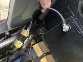
View attachment 268993that’s the grounding point that was used originally as the other one is not accessible
Maybe this is the issue - this is a seat base bolt right? Apparently those bolts have a protective coating, see [Guide] Seatbase stud bolt Earth / GND connection
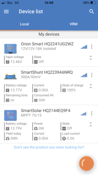
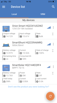
No. It looks ok to me. When the DC-DC comes on it raises the voltage of the LB to 14.2ish so the MPPT thinks it is fully charged and goes into absorption mode.Is the MPPT the problem thus?
It’s all to do with the small differences in the voltage that each box is seeing and the fact you LB is near full or full. The MPPT is seeing a slightly higher voltage so is switching mode before the DC-DC.
You could run the LB down a bit so it has room to take a proper charge and see how it all goes.
Also, if the differences are now constant you could tweak the charge settings so allow for the difference (e.g. 14.3v on the MPPT and 14.2v on the DC-DC - made up figures by the way).
It’s still a little odd that your shunt is seeing a lower voltage (considering it is so close to the battery) so I would make sure all
Its connections are clean, especially the one to the chassis.
No, not in your setup.Given it's all Victron, there's no setting or logic that actively switches the solar off when the DC-DC is running is there? Or even an actual relay in the circuit somewhere that disconnects the solar on engine run?
Still too high.Shunt chassis side to ground bolt is 0.12 on multimeter
Maybe this is the issue - this is a seat base bolt right? Apparently those bolts have a protective coating, see [Guide] Seatbase stud bolt Earth / GND connection
I mean if your ground point is the seat base stud this could very well be the root cause of all weirdness. The ground point has to be really clean and seat bolts are definitely NOT intended for that purpose.
So, in my shoes, what would you do?Still too high.
I mean if your ground point is the seat base stud this could very well be the root cause of all weirdness. The ground point has to be really clean and seat bolts are definitely NOT intended for that purpose.
So, in my shoes, what would you do?
Basically there's two choices: either you 1) dig out the official ground point from about the middle of seat base or 2) clean up the seat base stud one as was described in the thread I linked: [Guide] Seatbase stud bolt Earth / GND connection.
I haven't done the cleaning and don't know how hard that would be - in any case you want to be sure the connection to chassis is stellar so anything other than the official grounding point would need a measurement to be sure.
Tightened up super tight and got reading 0.08 how is that?Basically there's two choices: either you 1) dig out the official ground point from about the middle of seat base or 2) clean up the seat base stud one as was described in the thread I linked: [Guide] Seatbase stud bolt Earth / GND connection.
I haven't done the cleaning and don't know how hard that would be - in any case you want to be sure the connection to chassis is stellar so anything other than the official grounding point would need a measurement to be sure.
I’m assuming your negative bus isn’t connected like your diagram. It should be connected to chassis not the negative of the leisure battery. Only the shunt connects to the negative of the leisure battery.Waiting for daylight. In mean time reposting this in case sheds any light.
This is as I understand the system under the drivers seat. I will attempt the same for the rear wardrobe electrics too.
The cloud shaped middle of the page where it says ‘under seat ?’ With grey wires x2, a brown wire x1 and red wire x1 presumably communicates with rear wardrobe unit?View attachment 268918
Only the shunt connects to LB -ve post yesI’m assuming your negative bus isn’t connected like your diagram. It should be connected to chassis not the negative of the leisure battery. Only the shunt connects to the negative of the leisure battery.
Similar threads
- Replies
- 17
- Views
- 416
- Replies
- 7
- Views
- 1K
- Replies
- 8
- Views
- 1K
- Replies
- 8
- Views
- 707


