Yes momentary switchThank you
So to be sure they should be momentary on and not cycle through on off like switch. Right ?
You are using an out of date browser. It may not display this or other websites correctly.
You should upgrade or use an alternative browser.
You should upgrade or use an alternative browser.
Traction Control - ESC/ASR & HDA switch retrofit
- Thread starter Chickybumps
- Start date
Mehkor
Member
Thank youYes momentary switch
pin 6 is 12v i just run a wire with new connector as above to the switch and back into a joint for pin 6 to get power, you can run the wires through the drain for the A/C its easiest way its a pain to get the the abd module you need to remove battery and undo the fuel filter to get it out and up enough to get the cover off the connector budget a good few hours to do it properly you may need some coding to get the asr to turn off
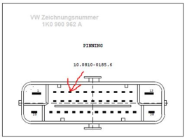
In the Connector the fields A2 to A5 should be empty. For your orientation: Pin 1 and 25 are red, Pin 13 on the other end is brown and Pin 38 is not connected.
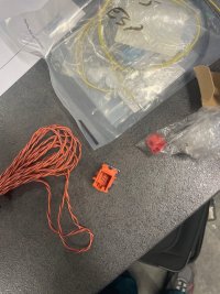
just get soldering iron and gently remove some of the insulation from pin 6 thats KL15 12v get a twisted pair of wires and run them both to the switch in the dash the switch is a momentary switch so check with multimeter the connections basically then you have a pair of wires one with the new pin you click into T4 and one soldered to pin 6 12v if you have the OEM part number dash switch then it will have 4 pins, one is earth one is 12V for lights i never bother with, the other 2 connect when you press the button down you want those 2 it doesnt matter which way you wire those 2 together as its just creating a connection to aplly 12v to deactivate the esp
just get soldering iron and gently remove some of the insulation from pin 6 thats KL15 12v get a twisted pair of wires and run them both to the switch in the dash the switch is a momentary switch so check with multimeter the connections basically then you have a pair of wires one with the new pin you click into T4 and one soldered to pin 6 12v if you have the OEM part number dash switch then it will have 4 pins, one is earth one is 12V for lights i never bother with, the other 2 connect when you press the button down you want those 2 it doesnt matter which way you wire those 2 together as its just creating a connection to aplly 12v to deactivate the esp
aasnesen
Member
Was probably a bit messy worded.I Connector skal feltene A2 til A5 være tomme. For din orientering: Pinne 1 og 25 er røde, pinne 13 i den andre enden er brun og pinne 38 er ikke koblet til.
bare hent loddebolt og fjern forsiktig litt av isolasjonen fra pinne 6, dvs. KL15 12v, få et tvunnet par ledninger og kjør dem begge til bryteren i dashbordet. par ledninger en med den nye pinnen du klikker inn i T4 og en loddet til pinne 6 12v hvis du har OEM delenummer dash-bryter så vil den ha 4 pinner, en er jord en er 12V for lys jeg aldri bryr meg med, den andre 2 koble til når du trykker ned knappen du vil ha de 2 det spiller ingen rolle hvilken vei du kobler de 2 sammen, da det bare oppretter en tilkobling til aplly 12v for å deaktivere esp
On the connector for ABS: pin4 and pin 6 to be connected.
Where should this be connected to the TC button?
And can I take 12v from another place than from pin 6 on ABS? For example from the start-stop button?
aasnesen
Member
As I read from earlier in this thread, I can use pin4 from start-stop button to pin4 TC button instead of pulling cable to pin6 ABS connector.Was probably a bit messy worded.
On the connector for ABS: pin4 and pin 6 to be connected.
Where should this be connected to the TC button?
And can I take 12v from another place than from pin 6 on ABS? For example from the start-stop button?
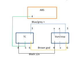
So then I conclude that I connect pin4 from ABS connector to pin5 TC switch. Pin4 TC switch to pin4 start-stop switch. Is there more that needs to be connected in the TC switch?
Only -ve brown and +ve grey/blue for the switch illumination if required.As I read from earlier in this thread, I can use pin4 from start-stop button to pin4 TC button instead of pulling cable to pin6 ABS connector.
So then I conclude that I connect pin4 from ABS connector to pin5 TC switch. Pin4 TC switch to pin4 start-stop switch. Is there more that needs to be connected in the TC switch?
aasnesen
Member
Does anyone have a flow diagram for the start / stop button?Only -ve brown and +ve grey/blue for the switch illumination if required.
aasnesen
Member
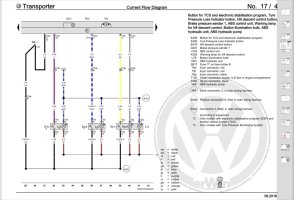
On this diagram pin 4 abs to pin 5 TC button
I have a t32 2017 no traction button but when me and some friends all got stuck in snow & ice on the drive while staying at an aibnb farm my van was the only one to make it out without a toe. I think it might be smarter than it looks.
My first retrofitted traction control switch deactivates ASR only
View attachment 64067
to actually work as a ESC deactivation switch
View attachment 64069
More details to follow soon
Any news here Robert?
I have switched from ASR OFF to ESC OFF
aasnesen
Member
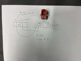
Have connected according to this self-made drawing. Everything works except for the light in the button when it is activated. Is there anyone who can give a tip on how I can make the button light up?View attachment 141459
Can this be right?
Traction Control Switch has only illumination light inside. According to ERWIN wiring diagram there is no indication light.Have connected according to this self-made drawing. Everything works except for the light in the button when it is activated. Is there anyone who can give a tip on how I can make the button light up?
Why do you want your switch to indicate it if you are getting this via Instrument Cluster dedicated LED?
On a side note, HDA switch has indication light built in but even if this is wired in it still doesn't work.
Similar threads
- Replies
- 4
- Views
- 992
- Replies
- 3
- Views
- 295
- Replies
- 93
- Views
- 31K
- Replies
- 29
- Views
- 52K

