Leisure power upgrade

Don't forget that the smart shunt needs to be the only thing connected to the LB negative terminal. Then all other negatives connect to the other side, generally via a busbar or via chassis ground.

You won't need any connection to the SB for the shunt, all it's measuring is in/out for the LB.

You'll have negatives from the Orion 50a, the MPPT, the Ablemail, the EHU charger - and the negative from the Sargent (presumably that's all your DC loads).
Thanks. I will do a more detailed drawing when I get all my stuff.
And more detailed drawings of each component, where it’s going to live, what exact terminals and fuses it will need and thickness and where each cable goes.
I will also keep the thread updated with my progress.
I’m planning on making brackets that I can attach to my pop top to fix my huge solar panel on. With a windbreak moulding on the front.
I want it so the panel can be replaced by just unscrewing it from the brackets fixed permanently to my pop top.
 
Bummer, sorry Gord. Inflation I guess. I would give them a bell though and do a bit of begging, mention some fool of a member of the forum said you would get free advice. They are good folk!
Once I’ve got a better wiring diagram worked out and am ready to pull the trigger on the roamer I will email them with it and ask for some advice
 
That’s great thanks.
Think I will hang fire on ordering the cables until I’ve worked out how long they are going to be. Also will wait and see what terminals etc are on various bits once they arrive so I’ve got a better idea of what to order.
By then I will hopefully have a wiring diagram on all my install. Will need help with that too ;):D:geek:
I’m going to buy the roamer 230SMART4 battery after @Dellmassive’s fantastic help of comparing it with the fogstar eco. Thanks Lee.
The roamer is a far superior battery so I don’t mind paying the extra £300 for it.
I don’t know if you’ve found a discount offer for the Roamer battery but you can get the 230ah battery using this discount code from Mispronounced Adventures for £769.00.
 
Can you send me link mate?

Seat base at £799 non seat base at £769, limited time....
 
Started making a very basic fag packet wiring diagram using my very limited knowledge.
I’ve based this on one of @Dellmasives wiring diagrams that I’ve adapted.
I’ve still not worked out length and thickness of cables or what sizes of fuses to use.
Does this look ok?
I appreciate it’s a good bit more complicated than that but I’m a quick learner.
If anyone has a better more detailed wiring diagram that I could follow or adapt to my set up that would be great thanks.

View attachment 254259
Have a look on Nomah (used to be called Climbingvan) for some excellent examples of wiring diagrams and explanations.

A few initial thoughts on your diagram:

From the LB positive I would suggest single cable to a main fuse (big enough to cover max total load (plus a bit) but small enough to be less than cable capacity) then to isolator switch then to a positive busbar. All other positives attach to this busbar and are fused at the busbar end to protect the cable. You can get a neat fused busbar (1 mega, 4 midi) from places like 12voltplanet which is a neat solution.

From LB negative a single cable to shunt then to a negative busbar. Other nearby negatives to busbar and busbar to chassis. Distant negatives to chassis.

Solar panel to double pole isolator (allows you to switch off/isolate panel for maintenance or power management) then to MPPT then to pos busbar. No fuse needed at MPPT end of positive cable as MPPT is fused/protected (fuse required at busbar end to protect cable).

Ablemail connects to DC-DC only (3 cables, one into each connection of DC-DC). These can be small gauge cables as only carrying 3A. Clear instructions provided with the Ablemail.

If you draw in colour using red for pos and black for neg it makes it much clearer to see what is going where.

Hope that makes sense! Think I did about 2000 diagrams before getting it sorted!!
Thanks very much.
This is exactly what I was hoping to hear.
I’ve been reading a lot of threads on this subject trying to learn and I actually understood everything you have said.
I’m on my 3rd drawing already.
I will try make the next one much more detailed and include the bus bars, colour code positives and earths and show lay out/position In my van. I will also amend my mistakes. Cheers :) :thumbsup:
 
Have a look on Nomah (used to be called Climbingvan) for some excellent examples of wiring diagrams and explanations.

A few initial thoughts on your diagram:

From the LB positive I would suggest single cable to a main fuse (big enough to cover max total load (plus a bit) but small enough to be less than cable capacity) then to isolator switch then to a positive busbar. All other positives attach to this busbar and are fused at the busbar end to protect the cable. You can get a neat fused busbar (1 mega, 4 midi) from places like 12voltplanet which is a neat solution.

From LB negative a single cable to shunt then to a negative busbar. Other nearby negatives to busbar and busbar to chassis. Distant negatives to chassis.

Solar panel to double pole isolator (allows you to switch off/isolate panel for maintenance or power management) then to MPPT then to pos busbar. No fuse needed at MPPT end of positive cable as MPPT is fused/protected (fuse required at busbar end to protect cable).

Ablemail connects to DC-DC only (3 cables, one into each connection of DC-DC). These can be small gauge cables as only carrying 3A. Clear instructions provided with the Ablemail.

If you draw in colour using red for pos and black for neg it makes it much clearer to see what is going where.

Hope that makes sense! Think I did about 2000 diagrams before getting it sorted!!
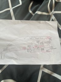
Here’s my latest diagram.
I’ve included a fused positive bus bar and an earth bus bar. I’ve also colour coded the positives and earths and sorted my mistakes. I’ve also given a vague idea of where about in the van they are going.
The MPPT, double pole isolator and blue smart charger will be in cupboard at the back beside the Sargent.
All the rest the DC-DC, LB, ablemail, smart shunt and bus bars will be below the microwave in the kitchen. Plenty room in there.
My solar panel is on its way. Have the DC-DC and about to order the Roamer 230SMART4 battery.
Once I’ve worked out what cables and connectors I need I will order the rest from 12v planet.
Intend on starting this soon.
All advice from everyone is appreciated
Cheers

IMG_6562.jpeg
 
Looks good.

Is the SB to DC-DC wiring already there?

If not, I'd suggest a slight alteration to your wiring there, stick an 80a Megafuse at the SB end of that cable, and a 60a midi fuse at the DC-DC end.

Also, take the SB connection for the Ablemail and attach that to the DC-DC side of the 60a midi fuse.
Ablemail positive for the LB just goes to your positive busbar.

Oh and use the auxiliary input on the smart shunt to monitor the SB, you can do this with a ring terminal on the other side of the midi fuse (the same one the Ablemail is also connected to). This also means the shunt will still see the SB voltage if the fuse blows.

Lastly, take the shunt voltage input for the LB from the battery side of the main isolator, again this means that when you flip the main isolator switch, the shunt can still see the battery voltage and it's still powered on. It's just powering the shunt so safe to still have connected with the main isolator off.

Fyi you'll need 16mm² cable for all the Orion 50a wiring. And heatshrink to take it up to the correct size for the strain relief cover.

1000008410.jpg


Oh and do you have an ignition signal wire? From a previous install, if there was one? If so, use that as the remote on/off for the Orion, just much simpler than setting engine shutdown detection.
 
Last edited:
Looks good.

Is the SB to DC-DC wiring already there?

If not, I'd suggest a slight alteration to your wiring there, stick an 80a Megafuse at the SB end of that cable, and a 60a midi fuse at the DC-DC end.

Also, take the SB connection for the Ablemail and attach that to the DC-DC side of the 60a midi fuse.
Ablemail positive for the LB just goes to your positive busbar.

Oh and use the auxiliary input on the smart shunt to monitor the SB, you can do this with a ring terminal on the other side of the midi fuse (the same one the Ablemail is also connected to). This also means the shunt will still see the SB voltage if the fuse blows.

Lastly, take the shunt voltage input for the LB from the battery side of the main isolator, again this means that when you flip the main isolator switch, the shunt can still see the battery voltage and it's still powered on. It's just powering the shunt so safe to still have connected with the main isolator off.

Fyi you'll need 16mm² cable for all the Orion 50a wiring. And heatshrink to take it up to the correct size for the strain relief cover.

View attachment 255022


Oh and do you have an ignition signal wire? From a previous install, if there was one? If so, use that as the remote on/off for the Orion, just much simpler than setting engine shutdown detection.
The wire from SB to LB is in but it’s dangerously thin so is getting replaced so will fit the fuses as you describe. I will look for an ignition feed for the Orion remote and put one in if not.
I understood all that advice thanks and will wire things up accordingly.
I will order some 16mm cable for earth bus bar and SB to DC-DC to LB and to fused bus bar and some heat shrink too.
What size of cable will I need for the rest of my install?
I know I will need special cable for the solar panel to the isolator then to MPPT.
What PV isolator do you recommend?
Also my volt meter is sh1te and needs upgraded before I start.
Got any suggestions on a half decent one that’s not super expensive?
Thanks
 
On cable sizes:

16mm² from SB to DC-DC, and for both negative and positive outputs. Going to busbars. 60a midi on the fused positive busbar.

MPPT - 6mm² PV cable from the panel to the isolator
6mm² regular cable from isolator to MPPT and from MPPT to fused busbar. Check the manual for fuse size but with the 100/30 it'll probably be 40a

Now, for your main wiring - positive from battery to mega fuse to isolator to fused busbar AND negative from battery to shunt to busbar to chassis ground, there's 2 ways to go...

You currently don't have any big amp devices, so 16mm² which is capable of 110a is fine.

However... You have the battery capacity and solar capacity with the 230ah, which can do 300a continuous discharge, for a 3000w inverter!

So, what I would do in your situation, is up your cable sizes for these short runs, to 50mm² which can handle 345a - this is overkill, yes - but you can just fuse for your current loads, and then if, or when you decide to install an inverter, you'll not need to replace any wiring. Just add/replace a couple of fuses and you're good to go!

I'd also leave the Megafuse slot on your fused busbar free for this option.

1000010181.jpg
That's 50mm² cable on my install, it's not that hard to manage.
 
Last edited:
I know I will need special cable for the solar panel to the isolator then to MPPT.
What PV isolator do you recommend?
The panel will come with mc4 connectors, on about 1m of cable. You'll want 6mm² PV cable for the run from the mc4 connectors to the isolator.


If you have the space, use a proper double pole pv isolator. I didn't have space so I'm using a simple positive isolator switch which still works fine.
 
The panel will come with mc4 connectors, on about 1m of cable. You'll want 6mm² PV cable for the run from the mc4 connectors to the isolator.


If you have the space, use a proper double pole pv isolator. I didn't have space so I'm using a simple positive isolator switch which still works fine.
That’s great thanks.
Plenty room in cupboard beside the Sargent for a proper double pole isolator. Have you got a recommendation for one I can add to my shopping list?
Also amended my diagram

IMG_6563.jpeg
 
That’s great thanks.
Plenty room in cupboard beside the Sargent for a proper double pole isolator. Have you got a recommendation for one I can add to my shopping list?
Also amended my diagram

View attachment 255025
12v planet are my go to for stuff like this, you can't go wrong with their stuff. Just get a decent order together to get free postage :rofl:

 
Oh and use the auxiliary input on the smart shunt to monitor the SB, you can do this with a ring terminal on the other side of the midi fuse (the same one the Ablemail is also connected to). This also means the shunt will still see the SB voltage if the fuse blows.

Lastly, take the shunt voltage input for the LB from the battery side of the main isolator, again this means that when you flip the main isolator switch, the shunt can still see the battery voltage and it's still powered on. It's just powering the shunt so safe to still have connected with the main isolator off.
If you do this consider fusing the sense wires as near the connection as you can as you are bypassing the fuses/isolator. Personally I prefer master fuses/isolators to be absolute and cut everything off rather than having upstream connections to worry about.

Also my volt meter is sh1te and needs upgraded before I start.
I have this rather nice one from UniT - the DC clamp meter is excellent to have to hand - even if sometimes I just use it to hang the meter off something

 
The cables with the smart shunt do come fused, they use tiny 1a glass fuses.
Yep - but in the Victron diagrams they tend to show them with the fuses at the smart shunt end - if they're going direct to batter terminals past isolators and fuses I'd prefer them the other way around as it's the unfused length of the cable getting crushed to something grounded that would worry me.
 
I used this double pole isolator in this housing.

As mentioned, the SB to DC-DC fuse needs to be at the SB end. MIDI fuses are much smaller. You don’t need one at the DV-DC end as there is no output from the DC-DC.

Depending on your layout you don’t need a neg cable running from the LB to the rear. Ground the LB to the underwear ground point and connect the rear neg busbar to a suitable ground point at the back (there is one in the rear corner behind the trim pretty much in line with the rear light).

Personally I connected the AMT direct into the Orion as your plan (and instructions) to keep the cables short and neat. It may be different with the XS but was fine with my 30A version.

Connecting the shunt aux to the SB feed (fused as RT says) as mentioned by TallP is a great idea and gives you extra info all in the one app.

Looking good.
That’s great thanks I will pick up that PV isolator and housing.
Have you got a similar suggestion for the main isolation switch in between LB positive mega fuse and fused bus bar ?
 
Back
Top