VW T6 Custom PID codes for DPF

7E0 22208C - soot mass measured
can0 7E8 [8] 05 62 20 8C 01 DC AA AA
(hex) 01DC => (dec) 476 => 4.76g ((A*256)+B)/100

I think we need to adjust the formula for T6 EU6 engines - 654.63 grams just doesn't make sense.
SootMeasured_Unsigned_PID_Test-a.png


Realised that on T6 EU6 engines "Soot mass measured" gets also negative values both in ODIS and VCDS.
So presumably "A" should be treated as signed integer.
SootMeasured_PID_Test-a.png


Now the result aligns with VCDS.
SootMeasured_Dash.png
 
Now the result aligns with VCDS.
That’s good.

Probably not very useful though, I think this is the raw sensor value from which the calculated soot value is produced, through applying a secret black magic formula laid down by vw gods at the great ECU creation.
 
  • Like
Reactions: mmi
Catching up :grin bounce:

Looks sweet and seems to do the trick!

Meanwhile, I’ve dropped the ball on this for a while.

But as for what’s next I did order 2nd hand alarm controller as I don’t have it from factory. I’m probably not about to retrofit it fully but that module includes inclinometer G384 which perhaps can be read without enabling the full alarm functionality… maybe. Now just should find energy to wire it up and test, it would be pretty sweet to get roll / pitch angles to Car Scanner.

63437846-9808-428E-BA99-DF0A4049E47D.jpeg
 
yet another controller to monitor - Parking heater (Webasto)
Indeed - T6 Aux Batt is read from controller 18 - Aux.Heater (credit @n10n )
1664096938901.png
Perhaps we need also these from ABS :inlove:
1658387576833.png
Well, those are already part of Connection profile Volkswagen > OBD-II/EOBD Diesel DPF var. 1.
1664097065978.png


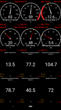
CS_12values_Screenshot_20220919-143835.png


It's now 6 different controllers monitored - ECU, DSG, AWD, A/C, Aux.heater, ABS :inlove:
Starts to slow down - but still updated every 2.6 seconds :)
 
This is just what I’m looking for, I’m going to try and get all the aux heater data on a screen, including logging the start stop information, this should help identifying when the heater has locked out.
 
This is just what I’m looking for, I’m going to try and get all the aux heater data on a screen, including logging the start stop information, this should help identifying when the heater has locked out.
 
  • Like
Reactions: mmi
But as for what’s next I did order 2nd hand alarm controller as I don’t have it from factory. I’m probably not about to retrofit it fully but that module includes inclinometer G384 which perhaps can be read without enabling the full alarm functionality… maybe. Now just should find energy to wire it up and test, it would be pretty sweet to get roll / pitch angles to Car Scanner.

Finally got around testing this as I have headliner and lot of trims removed for other stuff. Seems the inclination sensor can indeed be enabled in central electrics coding and it’s values read although not going for full alarm install.

Here, I’ve just plugged it in liu of rain sensor as it conveniently has necessary wiring available.

IMG_3627.jpeg

And here’s the readings from channel 52

IMG_3625.png

I’m definitely going to splice the alarm module in although I still have no idea if/how I can read it in CarScanner eventually.
 
CarScanner is nice for realtime observations and VCDS is good for measuring things, given you know exactly what to look for.

But I've been pondering on data collection on a larger scale for a while now. Both CarScanner and VCDS are only good if they're set up to read the exact parameters of interest - neither is really fit for collecting long term trend data or looking into bigger picture on the moment something happened. Also, if I would like to collect samples of how my van looks like now when there's thankfully still no major problems, I would need to go through vast amount of sensor measuring combinations and still there wouldn't be any confidence I would be able to capture something that would prove useful in the future.

So, what to do then? As data storage is cheap these days, why not just store all the CAN traffic, all the time? While this would not be necessarily the best resolution of measurements, it should capture everything various ECUs see of the vehicle state including all controls such as blinkers, throttle pos, gear etc. The problem, of course, is the same as in this thread overall - interpreting the data such as custom PIDs is not easy and not public information. However, if I have few years (hopefully) before major problems with the vehicle perhaps I can figure out some of the protocols meanwhile. Also, thinking really optimistically perhaps in a few years time I can just feed all the data to some AI and have it find trends and anomalies for me :)

I initially pondered on doing this sort of "black box" recording with a Raspberry Pi like in the above experiments. However, to record properly everything we would need to get both drivetrain and convenience CAN buses directly, it's not enough to look at OBD connector. I'm little bit hesitant of plugging cheap DIY stuff to drivetrain CAN on a permanent basis - probably fine when everything is working but it could be actually dangerous if it malfunctions and this kind of recording would need to work throughout years reliably, in -25 to +50 temperature range and endure moisture and vibrations. Also, quite a lot of small issues to solve with DIY solutions - such as how to not lose data when power is cut, packaging to withstand environmental challenges, how to automatically transfer recorded data to a cloud storage etc etc.

I studied ready made solutions and found CANedge2, which seems to be exactly what I'm looking for and then some bonuses: physically small and really well constructed, not very power hungry, capable of recording 2 CAN buses and 2 LIN buses simultaneously, GNSS + IMU, wifi for automatically transferring data out etc. The downside is the price: being kind of niche product it's not exactly cheap, then again considering the potential for years to come it might prove it's worth.

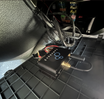
So, during weekend I installed CANedge2 to my fusebox cover and connected it to record drivetrain and convenience CAN -buses and LIN bus plus set up the automatic data transfers to Amazon S3. Right now, I'm still waiting to receive nicer DB9 connectors so some tidying up still tbd. Ofc I don't as of now have any custom data parsing set up so for now it's just a quite expensive but good quality tracker. Hopefully going forward I can actually extract meaningful vehicle data and look at their trends all the way back to this past weekend :)


1684133662095.png


1684131823368.png
 
Last edited:
CarScanner is nice for realtime observations and VCDS is good for measuring things, given you know exactly what to look for.

But I've been pondering on data collection on a larger scale for a while now. Both CarScanner and VCDS are only good if they're set up to read the exact parameters of interest - neither is really fit for collecting long term trend data or looking into larger picture on the moment something happened. Also, if I would like to collect samples of how my van looks like now when there's thankfully still no major problems, I would need to go through vast amount of sensor measuring combinations and still there wouldn't be any confidence I would be able to capture something that would prove useful in the future.

So, what to do then? As data storage is cheap these days, why not just store all the CAN traffic, all the time? While this would not be necessarily the best resolution of measurements, it should capture everything various ECUs see of the vehicle state including all controls such as blinkers, throttle pos, gear etc. The problem, of course, is the same as in this thread overall - interpreting the data such as custom PIDs is not easy and not public information. However, if I have few years (hopefully) before major problems with the vehicle perhaps I can figure out some of the protocols meanwhile. Also, thinking really optimistically perhaps in a few years time I can just feed all the data to some AI and have it find trends and anomalies for me :)

I initially pondered on doing this sort of "black box" recording with a Raspberry Pi like in the above experiments. However, to record properly everything we would need to get both drivetrain and convenience CAN buses directly, it's not enough to look at OBD connector. I'm little bit hesitant of plugging cheap DIY stuff to drivetrain CAN on a permanent basis - probably fine when everything is working but it could be actually dangerous if it malfunctions and this kind of recording would need to work throughout years reliably, in -25 to +50 temperature range and endure moisture and vibrations. Also, quite a lot of small issues to solve with DIY solutions - such as how to not lose data when power is cut, packaging to withstand environmental challenges, how to automatically transfer recorded data to a cloud storage etc etc.

I studied ready made solutions and found CanEdge2, which seems to be exactly what I'm looking for and then some bonuses: physically small and really well constructed, not very power hungry, capable of recording 2 CAN buses and 2 LIN buses simultaneously, GNSS + IMU, wifi for automatically transferring data out etc. The downside is the price: being kind of niche product it's not exactly cheap, then again considering the potential for years to come it might prove it's worth.

So, during weekend I installed CanEdge2 to my fusebox cover and connected it to record drivetrain and convenience CAN -buses and LIN bus plus set up the automatic data transfers to Amazon S3. Right now, I'm still waiting to receive nicer DB9 connectors so some tidying up still tbd. Ofc I don't as of now have any custom data parsing set up so for now it's just a quite expensive but good quality tracker. Hopefully going forward I can actually extract meaningful vehicle data and look at their trends all the way back to this past weekend :)


View attachment 198999


View attachment 198998
Very nice.

It Would be good to see what the extracted data looked like on an @mmi style Excell graph set. Start easy like, rpm + speed , or rpm + fuel rail pressure
 
Very nice.

It Would be good to see what the extracted data looked like on an @mmi style Excell graph set. Start easy like, rpm + speed , or rpm + fuel rail pressure

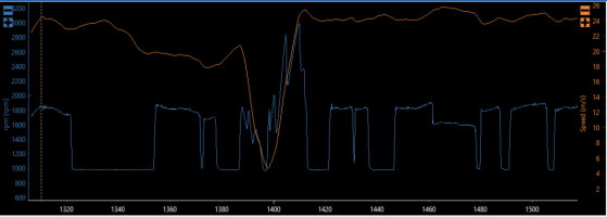
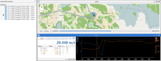
Really baby steps but something along those lines - I'm pretty sure I got RPM out and also water temperature but the scaling of temperature is still wrong.

  • In the map, I'm coming in from north to the tight hairpin and then accelerating towards west
  • From RPM plot you can see downshifting to the hairpin and acceleration pretty well, as well as coasting in various spots
  • PID from which RPM and water temp have been extracted has a frequency of 10Hz
  • GPS data has a frequency of 5Hz
  • Vehicle speed in tabular format is from GPS and expressed in m/s
1684304215227.png

Edit: speed vs rpm plot. Didn't notice it then but I had regen on
1684323680329.png

Very small progress but this already points out what I'm after: having now discovered how to get RPM out of the data I can take any past lump of data and compare RPM along with any other data.

Earlier in the thread we were digging into custom PIDs such as 22208B for getting Soot Mass Calculated. During the above run on Sunday I also had my CarScanner on so I tried to dig out how the CarScanner queries show on the internal canbus data. To do this, I converted the dataset into CSV format and started to just look up the hex values. And indeed, I can see requests for SootMassCalculated just fine:

Code:
  $ cat 20230514-test.csv | grep ";7E0;" | grep "22208B"
TimestampEpoch;BusChannel;ID;IDE;DLC;DataLength;Dir;EDL;BRS;DataBytes
  1684075635.437650;1;7E0;0;8;8;0;0;0;0322208B00000000
  1684075638.076550;1;7E0;0;8;8;0;0;0;0322208B00000000
  ... lot of requests ...
  1684077975.871100;1;7E0;0;8;8;0;0;0;0322208B00000000
  1684077977.792100;1;7E0;0;8;8;0;0;0;0322208B00000000

Strangely, the requests are shown on convenience can bus (;1; is the bus number, 1 is convenience in my setup).

But even more strangely, I can't see the responses at all in the data, and nothing with 7E8 ID:
Code:
$ cat 20230514-test.csv | grep ";1;" | grep ";7E8;" | grep "62208B"
$ cat 20230514-test.csv | grep ";1;" | grep "62208B"
$ cat 20230514-test.csv | grep ";1;" | grep ";7E8;"

Clearly, there's something going on which I don't as of now fully understand. My guess is that CAN GW is playing me up and synthesizing the responses from the already available data... or something. Anyway, this points out digging out the PIDs for various measurements is very different to the consumer side of the diagnostic port and I can't simply utilize the already discovered PIDs straight off.
 
Last edited:
Sigh... this is INTERESTING and definitely adds a new level how to stay informed what's going and especially what has been going on under the hood.
 
Sigh... this is INTERESTING and definitely adds a new level how to stay informed what's going and especially what has been going on under the hood.

Indeed. Of course, everything depends on finding the relevant PID’s and especially with the last discovery of not seeing diagnostic port responses on internal CAN it may prove quite difficult.

But hey, at least the hobby value is there :laugh:
 
Little bit of progress - I now can extract these bits of data:
  • odometer
  • rpm
  • oil temperature
  • water temperature
  • dsg temperature?
  • external temperature
  • measured speed km/h
  • displayed speed km/h
  • battery voltage ?
  • fuel level
  • dsg selector position
  • dsg coasting on/off
  • accelerator pedal on/off
  • brake pedal on/off ?
In addition, I have found a bunch of mystery signals I can't put my finger on just yet. Like this blue signal which I originally thought to be a very noisy accelerator pedal position - it correlates quite strongly with rpm (orange) and accelerator on (red). But it doesn't move with engine not running, so it's something else.

1684872467241.png


Learnings:
  • Unfortunately not many of the interesting sensors seem to be broadcast in buses by default. It appears that information architecture is such that most of the modules do not need to rely on sensor values of other modules directly - hence there is not much ask/respond traffic going on in the buses and raw sensor data just is not there.
  • There is actually not a single LIN bus in T6, but many. And they are not bridged so you can't monitor them all by tapping into one. Some might be queried via CAN though like in my test of the interior monitoring module earlier in the thread; I was able to query module angles over diagnostic CAN. LIN buses include at least:
    * climatronic <-> rear roof console
    * BCM <-> rain / light sensor and interior monitoring module
    * alternator <-> ECU
  • There is not actually just three can buses either. In addition to convenience, drivetrain and diagnostic buses there's a private can bus in between of BCM and cluster, and another one in between of ECU and something called "J849 Control unit for sensor electronics", it also connects to NOx sender 2. At least the cluster bus is isolated from other buses, I'm not sure about the ECU one. Perhaps the good stuff is hidden in these buses :laugh:
  • I am currently plugged into the climatronic LIN, as that was the most reachable - I took both the convenience CAN and LIN from climatronic connector. But that happens to be probably the most uninteresting LIN of them all... there's basically nothing happening normally. So, at some point I will need to revisit my wiring and pull the more interesting LIN wires to CANedge2 to get as complete as possible data collection.
Besides the above list of signals I've found so far I expect to be able to find out at least few more basic metrics, like steering wheel angle, running gear etc. In addition, I haven't looked at the switches at all - it's perhaps the least interesting data - but should eventually find many like blinkers, wipers, door open/close etc.

While it's slightly disappointing I will not be able to really see every sensor from internal buses directly, I might still be able to improve the data collection significantly beyond it's current state. CANedge2 can transmit hardcoded periodical messages to the buses, max 64 per bus. If I can figure out a static query message formats by which select sensor values can be asked for, I can also get their responses recorded and hence as part of my collected data. This should be good for at least 10-20 sensors probed with a reasonable frequency, say 1Hz, without overly flooding the buses. Ofc I could do pretty much the same by running the probing from CarScanner but then I would lose my current realtime dashboard.

Edit: J849 seems to be the DPF module, what a confusing name. Also, as the wiring diagram indicates the CAN for it to be same colour wires than the drivetrain CAN it's probably bridged on the ECU and not really a separate bus.
 
Last edited:
Like this blue signal which I originally thought to be a very noisy accelerator pedal position - it correlates quite strongly with rpm (orange) and accelerator on (red). But it doesn't move with engine not running, so it's something else.

Comparing blue signal against altitude (purple) and speed (brown) reveals it's probably either momentary consumption or engine load

1684933937995.png
 
My suspicious mind has been woken.

#1: I tapped into the drivetrain CAN from the floor channel under the gear stick - short run to the fuse box neighbourhood and the black/orange, brown/orange pair happened to be just on the top of the loom at the visible loom section. After investigating wiring diagrams / install locations more carefully, this is actually the run coming from ECU and headed to the DPF control unit via seat base.

#2: I've observed only a small number of active PID's in drivetrain CAN as compared to convenience CAN

#3: My drivetrain CAN data also has < 50% messages / minute compared to convenience CAN although drivetrain is supposed to be a "high speed" data bus

#4: I noticed the lesser number of PIDs / messages already earlier but my assumption was that drivetrain CAN is kept less busy in order to guarantee quick operation as safety -critical control units are on drivetrain CAN

#5: I still haven't been able to figure out why I don't see responses to my "soot mass calculated" requests, details in post #33

#6: None of the PIDs I've been able to interpret any signals from so far are originated from the drivetrain CAN

#7: Why would VW take drivetrain CAN wiring from ECU back to the seat base and then on to DPF while BCM connection point would be much closer? Wasting wire does not sound very VW-ish.

Put above together and I think I'm looking into some kind of a sub bus of drivetrain CAN currently, although the wire colours match. Maybe I'm not seeing the full depth of the drivetrain CAN? Perhaps ECU is acting as a gateway in this case as the DPF control unit is located underside of the vehicle? I suppose I need, in the name of the science of course, do some more wire work... the way to go is to take a temporary wiring from a known good drivetrain CAN and see if I get different results from there. Very eager to validate if my suspicions are right but unfortunately I probably don't have a chance to jump on this until next week earliest :(
 
Last edited:
Would an fairly easy to reach option to tap into drivetrain at Parking aid control unit (J446)?
1685024664187.png
 
Would an fairly easy to reach option to tap into drivetrain at Parking aid control unit (J446)?
I have a terrible wire lump there blocking the easy access, ton of retrofits :laugh:

But not to worry, I have pretty easy one right behind the lower dash panel next to the dimming control. It’s taken from steering wheel loom and I’ve fed my parking J446 side assist radars and Canm8 high beam module from there.

I should consider setting up can bus bars :)
 
Last edited:
Back
Top