Valence U27-12XP Lifepo4 Lithium Battery -- How We Done It --

Thanks for the feedback.

Yes, I do agree it is not 'fail safe' in its mode of operation and I did seriously consider using the 'NO' contacts on the relays (87 instead of 87a) and using the 'Invert relay' setting in the app. The disadvantage of not having any charging due to a fault condition as you described is more of a disadvantage to me than a failsafe on low temperature monitoring which I am unsure how often will actually be activated when the camper is in attended use during B2B and mains hook up charging. Also, there would be a continuous drain on the battery as the relays would normally be energised.

My 24/7 unattended charging is via the solar charge controller which has its own built in cut-off protection. If this were not the case, I would definitely have gone the fail safe configuration route.

I will monitor it and see how often the Low Temperature Disconnect (LTD) is active this winter before changing it. It is easily changed over (as described above) to give fail safe operation for those who are concerned or have other uncontrolled charging sources.
I think you’ve misconstrued my previous post,

1.Even if you used the NC contact on the bmv its still not fail safe.A safety circuit is always closed loop for a reason!....to fail safe.the way you’ve outlined it in your schematic is not a safety circuit.

2.you can potentially still have charging due to a possible fault condition,........but you Quoted this could be a disadvantage?.

3.if the safety circuit Is correct,then there would be no current drain Whilst the relays are energised!,as the current consumption for the relays would be provided by the ehu charger and the alternator respectively during operation!, you need to be switching the relay negatives and not the positives as the trigger control.
 
I think you’ve misconstrued my previous post

1. I am suggesting using the NO contact on the BMV and reversing the logic using the 'Invert relay' function in the app. The contact would, therefore, be active closed in normal charging on mode (and fail safe open). This would also require the NO contacts (87) to be used on the relays instead of the NC (87a) contacts. So they are active closed (and fail safe open).

2. Agree. Its an ambiguous argument!

3. There will be current drain when no charging is taking place because the relays in a fail safe configuration are always energised when the temperature (in this case) is >5 deg C.
You do not need to switch the negatives. A fail safe circuit just needs to 'fail safe' under fault condition; i.e. an open circuit loop due to component failure, fuse, wiring, etc. results in no charging. However, it does not matter which way you do it. It just needs to fail safe (no charge) when the circuit is open and the relays cannot be energised due to a fault condition.


I am leaning towards opting for the fail safe approach. I will test and update the diagram tomorrow. Thanks for raising the debate.
 
Well the biggest “AGM is fine I don’t need lithium” holdout finally cracked and picked one of these up Saturday. Fascinating guy, could have talked to him all afternoon about his projects and plans. A bit taken aback to find out these batteries are all 10yrs old though, didn’t think that technology was that old! He did say that in hindsight he could have priced these a fair bit higher so thanks to @Dellmassive for organising the buy. Another T6er was coming along that afternoon to pick the other one in the garage up so I guess I just missed whoever you are.
Don’t have any of the charging or connections yet, it’s all on its way, so haven’t had a look at the details yet, but it’s sitting at 12.9v when I measured it. Don’t know when I’ll get chance to do anything with it, I seem to be juggling three lives at the moment 54158B94-379C-4A7E-B210-7A8801010854.jpeg
 
Valence U27-12XP campervan install under the passenger seat – fail safe configuration

Here is the alternative wiring configuration for 'fail safe' operation. This will ensure in the event of a component, fuse or wiring failure, the relay controlled chargers are always off; i.e. they fail into a ‘safe mode’ and cannot accidentally charge the battery when you do not want to be.

Battery and charging v2 fail safe.png


In this configuration the relays are always active - the coils are energised – when the temperature is above 5 deg C (or as set). Any fault in the circuit will stop the relays being energised so the chargers cannot accidentally work.

This also means the relays have to be selected carefully to minimise the current drawn by them. Many high power automotive relays have low resistance coils between 80 and 120 ohms. Two relays can easily draw 200 – 400mA (0.2 - 0.4 Amps) and this would provide a continuous drain on the battery when no chargers are active.

To use the ‘fail safe’ configuration you need to look for relays with coil resistances over 200 ohms to keep the current low. This is easily achieved with low current rated relays where the coil resistances are much higher (because less energy is needed to pull in smaller contacts). I would suggest, therefore, using a low current (~1A) relay for the ignition/engine run signal feed. A 15A relay with a coil resistance of 225 ohms and a 1A relay with a coil of 950 ohms would only draw a combined current of 74mA at 13.5V when they are energised.

Another option is to move the +12V feed for the BMV contact to the OUTPUT side of the Smart Battery Protect. This would prevent accidental over discharge (LVD) and would also allow the relays to be manually disconnected - together with all other loads - when the van is not being used. To do this you can use the Victron Connect app to manually switch the loads off (or add a remote wired switch to the Battery Protect interface which it supports).


You also need to use the ‘Invert relay’ option in the BMV relay settings to use the 'fail safe' wiring configuration. This is because we have reversed the switching logic.

Screenshot_20201012-110428.png

D.
 
@Dilbert Thanks for the wiring diagram. Looks like the layout I will try and copy. A few questions from a novice. Is it usually to put the kill switch on the ground side. (When building rally cars we killed the live). You have two fuses in the starter battery feed. Is this to position them close to the terminals? and finally can you recommend the wire sizes on the heavy load runs? Many thanks.
 
A few questions from a novice.

1. I guess it is more normal to put the Kill Switch on the positive side but electrically it does not really matter as you are disconnecting the battery if either terminal is open circuit. I connected the battery isolator to the negative terminal as it was much easier to wire in on my setup due to the lack of room and there was only one connection on the negative and one on the battery side of the shunt which made it simple.

2. The two fuses on the starter battery feed are situated at either end of the cable; one very close to the starter battery, one close to the B2B charger. This protects the cable from either direction.

3. The cable sizes will depend on your exact setup; i.e. the maximum current your individual chargers can provide and the loads. You need to select the correct size cable to suit the maximum current and length of the cable to minimise voltage drop (and obviously overheating!). The biggest size cable will be on the negative connections (battery, shunt, main ground connection) as the combined currents from all the charging sources will pass through this. There is more information here: Diagrams, Schematics & Wires -- How I Done It -- and there is some good guidance on sizing and a calculator here: Cable sizing and selection | 12 volt planet There are also some more examples with cable sizes here: Diagrams, Schematics & Wires -- How I Done It --
 
Last edited:
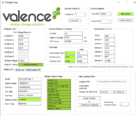
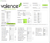
It's the weekend so I'm finally home with hopefully a bit of time to spend on the van. Big pile of Victron stuff waiting for me and I made up an RS485 connection lead while I had to wait for my Win10 laptop to update. And wait... and wait... Jeez I know I don't use it often but an hour and 15 mins before it would let me so much as click a button :mad: Hate windows.
Anyway eventually got these stats out.
Screenshot (1).pngScreenshot (4).png

Very happy with that, all the cells look in balance and it's sitting at 89% charge so there's no hurry to put it on charge or do anything.

One query I've got though, it's only got a cycle count of 36 which suggests it's virtually unused, but I read a comment on the excellent Mispronounced Adventures channel saying that's only the number of times it's gone to dead flat and that the WH discharge figure gives a better indicator of how much use it's actually had. In my case the 659269WH would equate to about 370 cycles. What's people's thoughts on this?
 
It's the weekend so I'm finally home with hopefully a bit of time to spend on the van. Big pile of Victron stuff waiting for me and I made up an RS485 connection lead while I had to wait for my Win10 laptop to update. And wait... and wait... Jeez I know I don't use it often but an hour and 15 mins before it would let me so much as click a button :mad: Hate windows.
Anyway eventually got these stats out.
View attachment 88330View attachment 88331

Very happy with that, all the cells look in balance and it's sitting at 89% charge so there's no hurry to put it on charge or do anything.

One query I've got though, it's only got a cycle count of 36 which suggests it's virtually unused, but I read a comment on the excellent Mispronounced Adventures channel saying that's only the number of times it's gone to dead flat and that the WH discharge figure gives a better indicator of how much use it's actually had. In my case the 659269WH would equate to about 370 cycles. What's people's thoughts on this?
That’s exactly how I understood it, coming from an electric vehicle (bus?) I’m guessing it was easy to plan the daily charging routines so not many cases of a full discharge especially if it had regenerative braking.
Somebody did mention on one of the threads that the batteries are 10 years old, I was a bit surprised by that but then realistically why else are they on the market unless the vehicle has been scrapped.
I haven’t put mine on a load test yet but all the figures look good as far as I’m aware.
Yes it was me that mentioned the 10yrs, it was what the seller told me when I went to pick it up. The firmware date is March 2011 which would bare that out (though doesn't prove it, you could put 10yr old firmware on a new battery) but I'm not bothered by that, as you say all the numbers look good.
 
I intend to manually control low temperature cutoff for now as it will very rarely be something I need to lookout for and will simplify the install. Maybe in my next bigger van I’ll do the whole works when I’ve got space to lay it out neatly. Anything wrong with bringing the 30A DCDC charger, 15A mains charger (rarely used) and 20A solar MPPT outputs all together to one hefty cutoff switch and run a single cable to the battery?
 
Anything wrong with bringing the 30A DCDC charger, 15A mains charger (rarely used) and 20A solar MPPT outputs all together to one hefty cutoff switch and run a single cable to the battery?

You also need to include the loads on the combined connection. There should not be anything on the other side of the switch other than the battery.

Keep the battery cable very short or, if it is of any length that could get compromised, add an additional larger fuse that can handle all the combined currents near the battery.

You can get fused distribution boxes that take all the fuses but you need more room for one of those.
The loads would be on a busbar the other side of the LBD, why would I need to have them on the other side of the switch? I only want to isolate the charging function, not the loads. I don’t understand why I can’t have 2 connections to the + terminal, one to loads and one from the chargers, surely it’s no different from having all the connections on the terminal?
 
The loads would be on a busbar the other side of the LBD, why would I need to have them on the other side of the switch? I only want to isolate the charging function, not the loads. I don’t understand why I can’t have 2 connections to the + terminal, one to loads and one from the chargers, surely it’s no different from having all the connections on the terminal?

I was assuming you wanted a complete battery isolator switch!

What you described will just isolate the chargers OK. However, some chargers need to see the Load battery first to self configure; e.g. Victron MPPT solar chargers. So you should also isolate the input to these and reconnect in the correct sequence. Mains chargers should be OK but B2B chargers may also be sensitive to the sequence. You would need to check the instructions.
No as I mentioned I’m just looking for a way of manually managing low temperature disconnect of the chargers. Thanks, I didn’t know that about chargers needing to see the battery first, I’ll do some reading up and experimenting.
 
If you have a Victron MPPT, you can leave it connected anyway and configure the built in low temperature cut-off; e.g. 5 deg C.
 
Can someone help with the following:

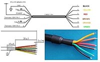
I ordered a USB RS485 cable as advised in this thread to connect to the battery but I hadn't realised the cable I ordered had 6 wires whereas the battery is a 5 pin connector. Can I still use this cable to connect to the battery and if so which wires go where? I've attached a diagram for further info. Thanks in advance.

USB RS485 cable pinout.jpg
 
Can someone help with the following:

I ordered a USB RS485 cable as advised in this thread to connect to the battery but I hadn't realised the cable I ordered had 6 wires whereas the battery is a 5 pin connector. Can I still use this cable to connect to the battery and if so which wires go where? I've attached a diagram for further info. Thanks in advance.

View attachment 88401
Yes you can. You only use 4 of the wires even though it's a 5 connector plug. Wire as follows

1) empty
2) ground
3 ) Data +
4) Data -
5) + 5v

Just cut the ends of the other 2 wires off.
 
If you have a Victron MPPT, you can leave it connected anyway and configure the built in low temperature cut-off; e.g. 5 deg C.
I don't have a BMV or temperature sensors, trying to do it on the cheap (or rather less exhorbitant!)
 
Back
Top