Valence U27-12XP Lifepo4 Lithium Battery -- How We Done It --

get this error message every time .
Any ideas ?

You get that error also if you are not running the program in administrator mode.

This is covered in previous posts. Close the application then Right click the program icon and 'run as administrator'.
 
Thanks for the advice I will try again tonight. My IT skills or lack of , are letting me down at the moment !
 
I give up . Time for a beer . When I try and run in administrator mode I get this . See pic .
I uninstalled- re installed . Same .:unsure:9089C1B9-F21B-4A59-BC3E-6537D5469188.jpeg
 
I had another attempt at connecting my battery to the Valence Diagnostics 12.12 running on a Window10 tablet.
The cable was checked yet again and is connected as the Valence Manual page 47 and according to the RS485 converter diagram. Once again I could not communicate with the battery.
5vDC polarity checked correct.
I switched data lines polarity and had communication straight away. The data lines are now opposite polarity to every document I have found online but it works!?

I’ve also tried to connect using the MacPro with WinoX 64 but that’s a non starter, more than one problem there I think so I’ll shelve that until I have my resident expert here to take the helm.

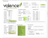
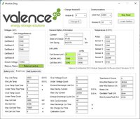
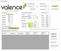
So the battery looks good as far as I can tell, note that the SOC is as delivered, I will charge it later. Only 37 Charge / Discharge cycles.
I’m puzzled as to what Temperature Sensors #5 & #6 are measuring, looking at other readings on this thread they all appear a bit random, my battery #5 is reading 253 degC.
In Event Log the Minimum Cell Voltage is showing as 2.408vDC which seems pretty low even by Valence minimum cut off voltage of 10vDC, the Event Log does not show any Under Voltage event.
Next I’ll make a full charge and run some tests on the trolling motor with the BMV712 in the circuit.
Thanks to those who have assisted me with the Valence Diagnostics communication problems:thumbsup:
D1DBF73D-37AD-42A2-B349-31CEADE2EBD2.jpeg6B28522D-EF09-47F9-9CD7-C189B3B9B052.jpeg5C1A05F3-5DB3-46FB-87CC-5D351454282A.jpeg
****************************************************************************************************************************************************************************************************************************
 
The data lines are now opposite polarity to every document I have found online but it works!?

Well done. :thumbsup:

The Valence A and B lines vs + and - appear to be opposite to most information. You have a 50:50 chance of getting it right!
 
I work offshore and most sensors we use on the ROV's have RS232 data protocols, (RS485 is the same idea but slightly different). When we fit a new bit of kit and the data string doesn't come through the first thing we do is swap the TX/RX. 9/10 it works fine. I've not seen your USB lead but some of them come with led's that blink according to what's working etc.

if you are having trouble with battery communications then i think you can download a program called 'hyperterminal', this is a simple dial up connection that will rear what ever you set it to, for instance you set the com port (whatever your USB is connected to) then the baud rate and dial up. if you're getting random numbers and letters come through then you have comms to the battery and the fault is elsewhere, software etc.
 
For anybody that’s looking to fit one under driver/passenger seat, here’s how it looks:

65D36275-ED02-495F-8AA1-8D88A644189B.jpeg29062212-D90E-4264-AC33-7DD9C2D48D6B.jpegFC10C821-FCE3-4314-9F25-216216654673.jpeg5930EC2C-713A-4492-AD25-97535C290072.jpegC20AFE82-9BAC-4872-9FB0-2B5A46F4A6DF.jpeg3D91C0D7-B0B7-480E-BE1B-BD62F4AA050D.jpeg9B6237D3-2786-4850-81BA-1EA21FC1E3B0.jpeg
 
So i currently have a mac and am looking to purchase a computer/tablet as cheap as possible to run the Valence software to check the life of my battery.

What do people recommend? I currently have an ipad also so the tablet/laptop will receive minimal use. So cheap and effective is the priority.
 
So i currently have a mac and am looking to purchase a computer/tablet as cheap as possible to run the Valence software to check the life of my battery.

What do people recommend? I currently have an ipad also so the tablet/laptop will receive minimal use. So cheap and effective is the priority.

There’s some options posted earlier in this thread:

 
Valence U27-12XP campervan install under the passenger seat

I finally got around to fitting the Valence LifePo4 battery under the passenger seat. The whole of the existing lead acid setup was first removed.


New lithium install main components:

Victron Blue Smart IP22 12/15 (mounted under the driver seat) – Mains hook up charging

Victron MPPT 75/15 – Solar charge controller (set with <5 deg C low temperature cut-off).

Sterling BB1230 – Battery to Battery charger for when engine running (configured with ignition ON run feed. [Unit will be replaced with Victron Orion 12/12-30 if and when it fails!].

Victron Battery Protect 12/65 – low voltage load disconnect to protect battery from over discharge (set at 11.5V).

Victron BMV-712 Smart Battery Monitor – configured to provide low temperature disconnect (<5 deg C) of both the Mains Charger [output disconnect] and Battery to Battery Charger [ignition run signal disconnected] via two external relays. Low temperature, high temperature, low voltage and high voltage BMV alarms were also configured.

All units above are currently set with their default Lithium charging profiles.


Physical Install

It is a tight squeeze to get the battery and all the components (except for the mains charger) into the space provided in the seat base.

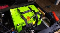
I finally decided to install the battery across the right hand side of the seat. Wooden runners were bonded in place to raise the battery above the seat base frame edges and mounting studs. This allowed the battery to be kept as near to the side as possible. A metal restraining strap was mounted across the front and a spacer and retaining bracket added to the rear. Note the RIB rotating seat base interfaces provided a bit more much needed height clearance which was helpful. The battery had to be moved forward of the seat base rear because the rear plastic cover panels are recessed inwards.

IMG_20201001_123124972.jpg

IMG_20201001_130304529.jpg


The BB1230 was mounted onto the left hand side of the seat base.

IMG_20201001_174050003.jpg


The MPPT, Battery protect and BMV shunt were mounted onto a panel fixed adjacent to the battery.

IMG_20201006_112554436.jpg


A battery isolating switch was added under the front of the seat. This disconnects the battery negative from the shunt.

IMG_20201008_162759580.jpg


Final wiring was tight and I protected the cables with split convoluted sleeving to provide mechanical protection. I wanted to make sure there was good physical integrity especially with the amount of energy being stored there!

IMG_20201010_125658252.jpg

IMG_20201010_122046312.jpg


The two low temperature cut-off relays were mounted at the front in some spare positions on the existing plastic frame.

IMG_20201010_125658252aa.jpg


The main BMV display module was mounted on the rear seat panel.

IMG_20201010_125715795_HDR.jpg


Next stage is to knock up a small external Battery Management System (BMS) based on the Arduino-XP-BMS project seb303/Arduino-XP-BMS My main requirement is to keep the internal battery BMS awake so that the cell block balancing can remain active.

D.
 
Looking good @Dilbert! How do the relays work for the charger/solar disconnect? Are they both wired into the BMV 712? Any chance you could share a wiring diagram at some point? Thanks in advance.
 
I’m interested in the low temp disconnect relay, I assume it only disconnects but requires a manual reset when above freezing. Is that the case?
 
How do the relays work for the charger/solar disconnect? Are they both wired into the BMV 712?

I assume it only disconnects but requires a manual reset when above freezing. Is that the case?

The BMV has its own relay single pole change over contact that you can program in the BMV settings. For this to work on temperature, you have to have the optional BMV temperature sensor.

You set a limit (in this case a temperature setting) to close the contact and another limit to open the contact. So it resets itself when the temperature rises. The two relays I have added are energised via this BMV contact so they both operate together.

The relays control the mains hook up charging and battery to battery (engine run) charging. The MPPT solar charger has its own programmable temperature cut-off setting. (Unfortunately only certain Victron products have this feature).

I will share some more detailed information tomorrow.
 
As promised, here is the diagram that shows the configuration of the chargers, low voltage battery protection and low temperature charge control.

Battery and charging v1.png

  • The Smart battery protect is configured (with the Victron Connect app is easiest) to provide low voltage disconnect of the load if the battery voltage goes below 11.5V.
  • The MPPT charge controller has built in low temperature cut-off that you can configure with the Victron Connect app. This is set to 5 deg C. (The MPPT receives its temperature data from the BMV via Victron’s VE.Smart network connection).
  • The Battery to Battery (B2B) charger is configured to require an Ignition +12V or engine run +12V to enable it to charge. For the Sterling BB1230 this requires it to be operated in ‘Mode 2’ or ‘Mode 3’. This Ignition/engine run signal is passed through RELAY 1.
  • The Mains hook up charger has its output going through RELAY 2.
  • The relays are controlled by the BMV-712 and this must also have the optional Temperature Sensor fitted to the positive terminal of the battery.
The relays are standard change over relays rated at 40A. The ignition/engine run signal relay does not need to be such a high current relay but this type of relay provides for easy termination of the connectors (and I had plenty of them!).

I chose to discreetly switch only the affected chargers, rather than isolate all chargers with one large relay, because some chargers need to ‘see’ the load battery first to operate correctly.

The relays are energised by the internal contacts in the BMV-712. The contacts are configurable via the BMV display or the Victron Connect app. The latter being much easier.
  • A fused positive feed* goes to the BMV display contact Common (COM) connection. The BMV Normally Open (NO) connection then goes to both relay coils (86).
  • The other relay coil connection (85) of both relays connects to ground (0V).
  • The relays use the normally closed contacts (87a) and common (30) to do the switching.
  • Under normal operation the relay is not energised and the normally closed contacts are made.
  • If low temperature is detected, the relays are energised and the normally closed contacts go open and remove the feeds. This then means [1] the Ignition +12V/engine run signal no longer reaches the B2B charger so it shuts down, and [2] the output from the Mains changer is disconnected from the battery.
*[Note: I took the +12V feed for the relays from the battery side of the low voltage Battery Protect. This was to ensure the low temperature charge protection would work in the event of the battery being below 11.5V at the same time. This obviously risks the relays discharging the battery below 11.5V as this current draw is unprotected. But the circumstances are hopefully very unlikely!].


This is the Victron Connect app BMV ‘Relay’ configuration menu. You will see I have also configured a high temperature protection as well as low temperature. I also set a minimum relay closed time of 1 minute to stop any rapid on-off-on switching.
Screenshot_20201011-121810.png


This is the BMV temperature setting sub menu where you can configure the ‘Set value’ to activate the relays and the ‘Clear value’ deactivates the relays.
Screenshot_20201011-121823.png


Hope this helps. Let me know if you have any questions.

D.
 
Thanks @Dilbert - that is very helpful :thumbsup:

Do you have several ground points across the system? Have you simply grounded to different parts of the chassis as appose to routing all grounds back to the battery?
 
Do you have several ground points across the system?

All the ground points for the local chargers and relay coils actually go back to the ground side of the shunt (I wanted to simplify the diagram). This side of the shunt has a 16mm² cable to the chassis. Otherwise the other loads are other local chassis connections.
 
As promised, here is the diagram that shows the configuration of the chargers, low voltage battery protection and low temperature charge control.

View attachment 87867

  • The Smart battery protect is configured (with the Victron Connect app is easiest) to provide low voltage disconnect of the load if the battery voltage goes below 11.5V.
  • The MPPT charge controller has built in low temperature cut-off that you can configure with the Victron Connect app. This is set to 5 deg C. (The MPPT receives its temperature data from the BMV via Victron’s VE.Smart network connection).
  • The Battery to Battery (B2B) charger is configured to require an Ignition +12V or engine run +12V to enable it to charge. For the Sterling BB1230 this requires it to be operated in ‘Mode 2’ or ‘Mode 3’. This Ignition/engine run signal is passed through RELAY 1.
  • The Mains hook up charger has its output going through RELAY 2.
  • The relays are controlled by the BMV-712 and this must also have the optional Temperature Sensor fitted to the positive terminal of the battery.
The relays are standard change over relays rated at 40A. The ignition/engine run signal relay does not need to be such a high current relay but this type of relay provides for easy termination of the connectors (and I had plenty of them!).

I chose to discreetly switch only the affected chargers, rather than isolate all chargers with one large relay, because some chargers need to ‘see’ the load battery first to operate correctly.

The relays are energised by the internal contacts in the BMV-712. The contacts are configurable via the BMV display or the Victron Connect app. The latter being much easier.
  • A fused positive feed* goes to the BMV display contact Common (COM) connection. The BMV Normally Open (NO) connection then goes to both relay coils (86).
  • The other relay coil connection (85) of both relays connects to ground (0V).
  • The relays use the normally closed contacts (87a) and common (30) to do the switching.
  • Under normal operation the relay is not energised and the normally closed contacts are made.
  • If low temperature is detected, the relays are energised and the normally closed contacts go open and remove the feeds. This then means [1] the Ignition +12V/engine run signal no longer reaches the B2B charger so it shuts down, and [2] the output from the Mains changer is disconnected from the battery.
*[Note: I took the +12V feed for the relays from the battery side of the low voltage Battery Protect. This was to ensure the low temperature charge protection would work in the event of the battery being below 11.5V at the same time. This obviously risks the relays discharging the battery below 11.5V as this current draw is unprotected. But the circumstances are hopefully very unlikely!].


This is the Victron Connect app BMV ‘Relay’ configuration menu. You will see I have also configured a high temperature protection as well as low temperature. I also set a minimum relay closed time of 1 minute to stop any rapid on-off-on switching.
View attachment 87869


This is the BMV temperature setting sub menu where you can configure the ‘Set value’ to activate the relays and the ‘Clear value’ deactivates the relays.
View attachment 87870


Hope this helps. Let me know if you have any questions.

D.
Your design with the relays is not ’fail safe’!,if the bmv failed or the fuse feeding it was blown or a loose connection etc,and the temperature dropped then you Could potentially damage the battery. You should invert the relay on the bmv.
 
Your design with the relays is not ’fail safe’!,

Thanks for the feedback.

Yes, I do agree it is not 'fail safe' in its mode of operation and I did seriously consider using the 'NO' contacts on the relays (87 instead of 87a) and using the 'Invert relay' setting in the app. The disadvantage of not having any charging due to a fault condition as you described is more of a disadvantage to me than a failsafe on low temperature monitoring which I am unsure how often will actually be activated when the camper is in attended use during B2B and mains hook up charging. Also, there would be a continuous drain on the battery as the relays would normally be energised.

My 24/7 unattended charging is via the solar charge controller which has its own built in cut-off protection. If this were not the case, I would definitely have gone the fail safe configuration route.

I will monitor it and see how often the Low Temperature Disconnect (LTD) is active this winter before changing it. It is easily changed over (as described above) to give fail safe operation for those who are concerned or have other uncontrolled charging sources.
 
Last edited:
Back
Top