I use straps and made a L shape bracket to hold it in place. Snug as a bug fit......How did you fasten it in under the seat please …??
I’d started to park more off piste last year until my accident
You are using an out of date browser. It may not display this or other websites correctly.
You should upgrade or use an alternative browser.
You should upgrade or use an alternative browser.
Roamer LiFePO4 Gen2 230Ah Seatbase battery -- "How I Done It" --
- Thread starter Dellmassive
- Start date
Got a few pics for us please?I use straps and made a L shape bracket to hold it in place. Snug as a bug fit......
Battery Roamer 230SB install in van . . .
been busy so haven't had the chance to post . .
We had this 100ah Renogy in there . . . (200A isolator, 125A MIDI fuse and cable under floor to passenger seat base.)
plus the Victron BMV712 shunt
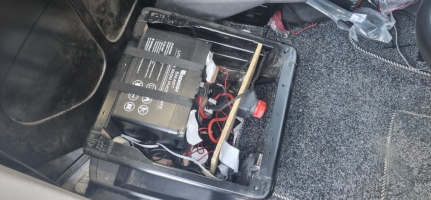
once removed we have this . .
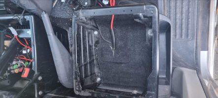
.
sizing the Roamer up . . .
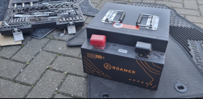
using the same ply wood and foam . .
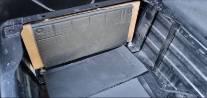
it was sitting too high.
the battery fits super snugg between the front lower lips of the seat base.
the bottom middle was being pushed up by my 20mm copex for the seat base link cables.
i also noticed that the ground stud domed nut under the carpet was also stopping the front of the battery going any lower . . . as was the seat spacer block under the carpet.
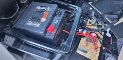
after a bit of jiggling, i decided to go with the foam pads on the rear back and bottom (to offer some cushioning to vibration). . . and remove the ply wood supports.
but the same straps to hold the battery down. (wrapped round battery and upper seat base, front to back)
+++
next up was the Victron shunt, i had this screwed to the front wood plate before . . . now i didnt have room, but there was a nice space down the side of the battery . .
so i used a 4x4 adaptable box 9 i have these to hand in the van anyway) to house the shunt . . ( i also cut the shunt ends off so it fitted in the box better)
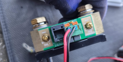
the battery uses M8 bolts, the shunt used M10 bolts.
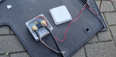
also noting what side went to the battery and what side to the van chassis . .
next us was the fuse and isolator switch . . .
i tried the 50mm2 cable at first, but i didnt have luggs big enough to fit . .
so i dropped down to 25mm2. . .
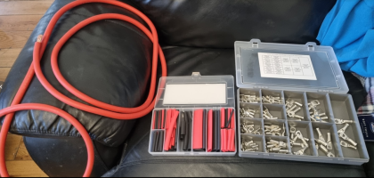
i also went for a 200A fuse in the MEGA fuse style . . M8 bolts.
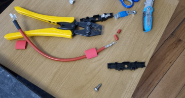
cable, fuse, fuse holder, heat shrink, crimper . . . . job done.
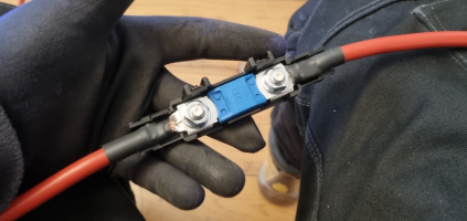
the long M8 bolts worked well holding down the main feed and the shunt temp/power lug.
i love these style of terminals . . they are great . . . especially with the integrated cover - awesome.
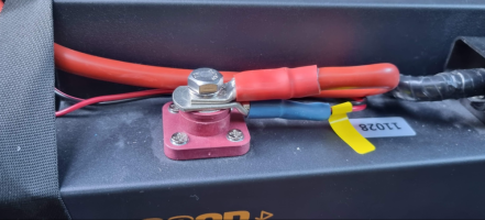
the fuse sits be the side . . . and the seat base bolt is used for the 25mm2 chassis ground ( paint scratch off with emery cloth for a good connection)
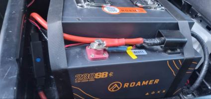
profile wise . . . we have this sticking above the base where the seat runners go . . . about 5-10mm.
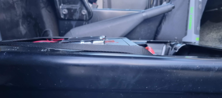
id already cut the carpet to allow the 20mm copex to sit back and allows the main cable to come up without chafing on the battery case . .
so at this point the isolator switch was fitted and screwed to a ply panel . .
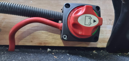
id used split 20mm copex to protect the "thin wall" 25mm2 cable from any rubbing from vibration for a bit of saftey . .
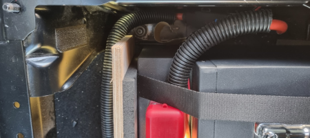
we ended up with this . . .
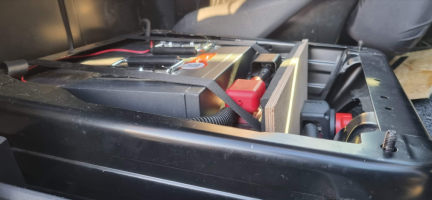
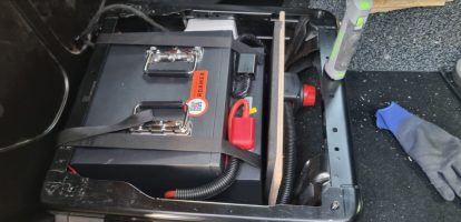
a quick check with the seat ontop showed good clearance . . .
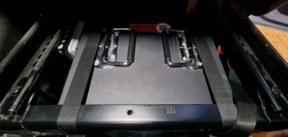
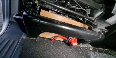
next up testing . . . . .

 roamer.com
.
been busy so haven't had the chance to post . .
We had this 100ah Renogy in there . . . (200A isolator, 125A MIDI fuse and cable under floor to passenger seat base.)
plus the Victron BMV712 shunt

once removed we have this . .

.
sizing the Roamer up . . .

using the same ply wood and foam . .

it was sitting too high.
the battery fits super snugg between the front lower lips of the seat base.
the bottom middle was being pushed up by my 20mm copex for the seat base link cables.
i also noticed that the ground stud domed nut under the carpet was also stopping the front of the battery going any lower . . . as was the seat spacer block under the carpet.

after a bit of jiggling, i decided to go with the foam pads on the rear back and bottom (to offer some cushioning to vibration). . . and remove the ply wood supports.
but the same straps to hold the battery down. (wrapped round battery and upper seat base, front to back)
+++
next up was the Victron shunt, i had this screwed to the front wood plate before . . . now i didnt have room, but there was a nice space down the side of the battery . .
so i used a 4x4 adaptable box 9 i have these to hand in the van anyway) to house the shunt . . ( i also cut the shunt ends off so it fitted in the box better)
the battery uses M8 bolts, the shunt used M10 bolts.

also noting what side went to the battery and what side to the van chassis . .

next us was the fuse and isolator switch . . .
i tried the 50mm2 cable at first, but i didnt have luggs big enough to fit . .
so i dropped down to 25mm2. . .

i also went for a 200A fuse in the MEGA fuse style . . M8 bolts.

cable, fuse, fuse holder, heat shrink, crimper . . . . job done.

the long M8 bolts worked well holding down the main feed and the shunt temp/power lug.
i love these style of terminals . . they are great . . . especially with the integrated cover - awesome.

the fuse sits be the side . . . and the seat base bolt is used for the 25mm2 chassis ground ( paint scratch off with emery cloth for a good connection)

profile wise . . . we have this sticking above the base where the seat runners go . . . about 5-10mm.

id already cut the carpet to allow the 20mm copex to sit back and allows the main cable to come up without chafing on the battery case . .
so at this point the isolator switch was fitted and screwed to a ply panel . .

id used split 20mm copex to protect the "thin wall" 25mm2 cable from any rubbing from vibration for a bit of saftey . .

we ended up with this . . .


a quick check with the seat ontop showed good clearance . . .


next up testing . . . . .

Roamer - Premium LiFePO4 lithium Leisure Batteries
Roamer SMART4, XTREME and HOME - the next generation in 12v 24V and 48V LiFePO4 lithium leisure batteries for campervans, motorhomes and boats. From 100Ah to 460Ah capacity with Bluetooth BMS, Victron GX integration, Active Balancing and low temperature charge protection. 5 Star UK support, 10...
.
Last edited:
Battery Roamer 230SB install in van . . . TESTING & 50A DC-DC Charge
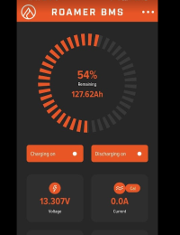
The current battery BMS was showing 54% (allowing headroom for the battery to pull full rate charge from the charger)
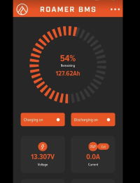
we have the Renogy DC50S 50A DC-DC charger . . . .
but had it set to 30A as we had seem some heat build up on the fuse block before when running at 50A . .
so to start with we were charging at 30A . . .
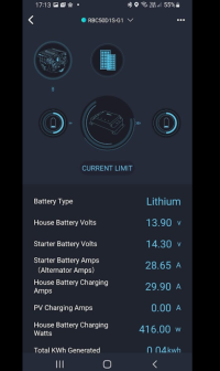
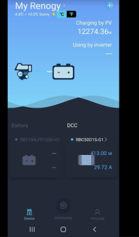
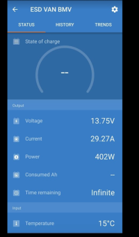
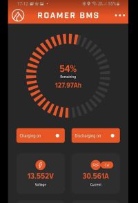
we can see the 30A on the victron, the Renogy, the Roamer. - so all measurements corollate.
keeping an eye on the thermals. . . . we see no issues . .
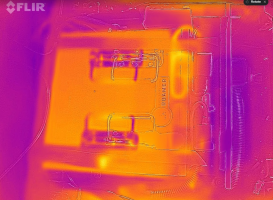
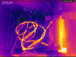
after re-doing the conection to the MIDI fuse block that showed heat build up last time . . .
it was time to turn up the charger . . . . 50A this time.
setting the Renogy to 50A / Lithium.
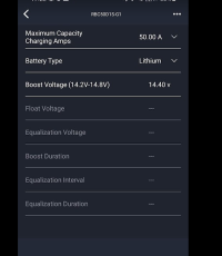
we get 50A charge out . .
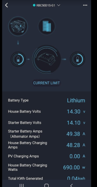
50A charge in . . .
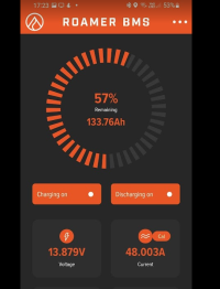
then let it run for 30mins at max power to see how it went . . .
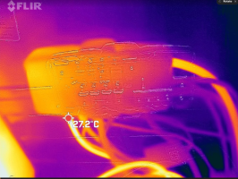
the fuse block warmed a bit . . . but below 30C so all good . .
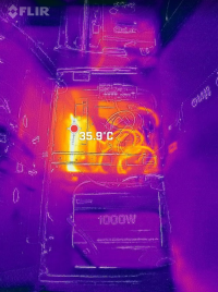
the charger reached about 35c which was fairly cool for 50A . . .
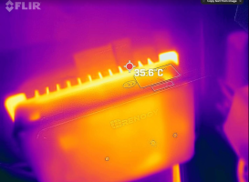
the battery, MEGA fuse, and isolator stayed cool as a cuecumber . . . . at ambient.
with a slight warming on the main cables as is expected.
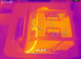
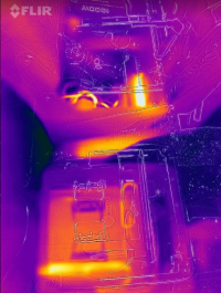
so all good . . .
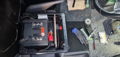
.
now time to fully charge the battery . . .
let the victron shunt sync to 100% itself.
them move all my IGN switched circuits over to the leisure battery ( Dash cam & Wifi adapter + USB charger blocks)
at that point ill meter out the load the van draws when parked . . .

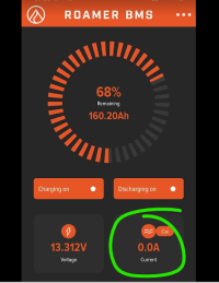
currently we are showing . . ( with just wifi and usb powered from LB , but all sleeping )
200mA ( 0.2A ) draw by the Victron shunt.
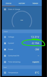
which is below the 500mA ( 0.5A) that the 230sb BMS can detect . . so its showing 0.0A atm.
all in all very happy with all the above,
and dont forget . .
this Roamer 230SB 230ah battery is effectively 5x 100Ah AGM batterys when taking into account the 50% dod.
.
more testing to follow . . . .
.

 roamer.com
.
The current battery BMS was showing 54% (allowing headroom for the battery to pull full rate charge from the charger)

we have the Renogy DC50S 50A DC-DC charger . . . .
but had it set to 30A as we had seem some heat build up on the fuse block before when running at 50A . .
so to start with we were charging at 30A . . .


we can see the 30A on the victron, the Renogy, the Roamer. - so all measurements corollate.


keeping an eye on the thermals. . . . we see no issues . .


after re-doing the conection to the MIDI fuse block that showed heat build up last time . . .
it was time to turn up the charger . . . . 50A this time.
setting the Renogy to 50A / Lithium.

we get 50A charge out . .

50A charge in . . .

then let it run for 30mins at max power to see how it went . . .
the fuse block warmed a bit . . . but below 30C so all good . .

the charger reached about 35c which was fairly cool for 50A . . .


the battery, MEGA fuse, and isolator stayed cool as a cuecumber . . . . at ambient.
with a slight warming on the main cables as is expected.


so all good . . .

.
now time to fully charge the battery . . .
let the victron shunt sync to 100% itself.
them move all my IGN switched circuits over to the leisure battery ( Dash cam & Wifi adapter + USB charger blocks)
at that point ill meter out the load the van draws when parked . . .

currently we are showing . . ( with just wifi and usb powered from LB , but all sleeping )
200mA ( 0.2A ) draw by the Victron shunt.

which is below the 500mA ( 0.5A) that the 230sb BMS can detect . . so its showing 0.0A atm.

all in all very happy with all the above,
and dont forget . .
this Roamer 230SB 230ah battery is effectively 5x 100Ah AGM batterys when taking into account the 50% dod.
.
more testing to follow . . . .

.

Roamer - Premium LiFePO4 lithium Leisure Batteries
Roamer SMART4, XTREME and HOME - the next generation in 12v 24V and 48V LiFePO4 lithium leisure batteries for campervans, motorhomes and boats. From 100Ah to 460Ah capacity with Bluetooth BMS, Victron GX integration, Active Balancing and low temperature charge protection. 5 Star UK support, 10...
.
Last edited:
Battery Roamer 230SB install in van . . . Charging Parameters
were using the Renogy DC50s DC-DC charger in the van . . on the same settings as the Renogy 100ah Lithium battery that was just swapped out.
but started noticing the battery BMS flagging a " charge off " notice . . .
the incoming charge was being blocked by the batterys BMS .
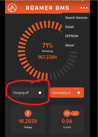
looking into it . . . . .
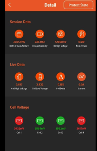
and checking the details tab we can see the COV "Cell Over Voltage" feature in action.
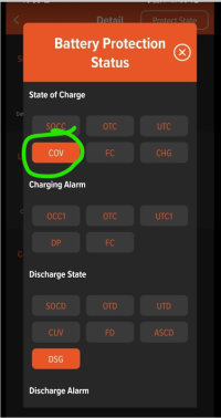
showing one of the cells was at high voltage . . . the battery BMS was cycling the incoming charge current to keep the cell voltage within limits. ( exactly what its supposed to do)
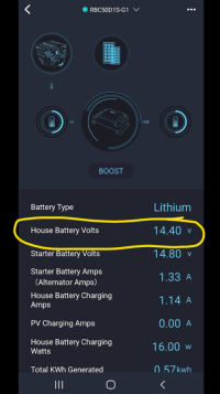
looking at the Renogy DC50S settings we can see the Leisure battery charge voltage is set to 14.40v
so i tweeked the setting and dropped the charge voltage down to 14.30v for a re test .
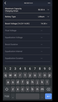
this settled things a bit . .
but the following day after the mornings top-up charge, the BMS was still cutting in and blocking the charge . . . . . "COV"
i popped over to Roamer batterys website to check the charge specs again . .
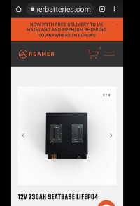
where it clearly shows 14.20v as the recomended charge voltage . . .
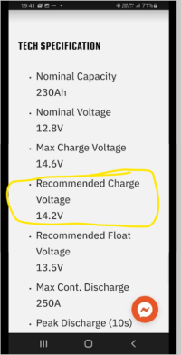
so i change the Renogys settings again . . . this time to 14.20v . . .
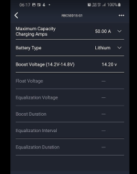
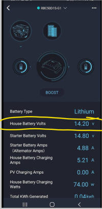
things started to settle down after that . . .
the BMS was showing 100% (235ah) and the battery was still taking <10A,
but the COV started to settle, and clear.
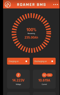
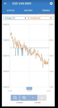
on the victron we can see the steady drop in current as the battery nears full capacity . .
...
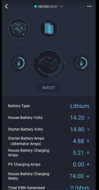
later on the same drive we was down to under 5A charge draw by the battery . .
.
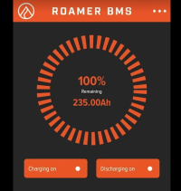
so all the above just goes to show the quality and outstanding features of the Roamer battery BMS.
as the spec-sheet shows - set your charge source to 14.2v
but . . .
if you cant change the setting, and its fixed like on the CTEK, NOCO and REDARC units as an example . . . . then feel happy that the Roamer battery will protect itself and deal with the matter.
NOTE that some DC_DC , MPPT chargers and mains chargers you can adjust the charge voltage . . . ie Victron, Renogy
...

 roamer.com


The upgraded BMS will passively balance all internal cells, and also support installation of up to 4 x 230SEATBASE batteries in series or parallel (one under each seat) with auto balancing for parallel connected batteries. It also provides a complete range of protections including low temperature charging.
++

 roamer.com
++
were using the Renogy DC50s DC-DC charger in the van . . on the same settings as the Renogy 100ah Lithium battery that was just swapped out.
but started noticing the battery BMS flagging a " charge off " notice . . .
the incoming charge was being blocked by the batterys BMS .

looking into it . . . . .
and checking the details tab we can see the COV "Cell Over Voltage" feature in action.

showing one of the cells was at high voltage . . . the battery BMS was cycling the incoming charge current to keep the cell voltage within limits. ( exactly what its supposed to do)

looking at the Renogy DC50S settings we can see the Leisure battery charge voltage is set to 14.40v

so i tweeked the setting and dropped the charge voltage down to 14.30v for a re test .

this settled things a bit . .
but the following day after the mornings top-up charge, the BMS was still cutting in and blocking the charge . . . . . "COV"
i popped over to Roamer batterys website to check the charge specs again . .

where it clearly shows 14.20v as the recomended charge voltage . . .

so i change the Renogys settings again . . . this time to 14.20v . . .


things started to settle down after that . . .
the BMS was showing 100% (235ah) and the battery was still taking <10A,
but the COV started to settle, and clear.

on the victron we can see the steady drop in current as the battery nears full capacity . .

...
later on the same drive we was down to under 5A charge draw by the battery . .

.


so all the above just goes to show the quality and outstanding features of the Roamer battery BMS.
as the spec-sheet shows - set your charge source to 14.2v
but . . .
if you cant change the setting, and its fixed like on the CTEK, NOCO and REDARC units as an example . . . . then feel happy that the Roamer battery will protect itself and deal with the matter.
NOTE that some DC_DC , MPPT chargers and mains chargers you can adjust the charge voltage . . . ie Victron, Renogy
...

Roamer - Premium LiFePO4 lithium Leisure Batteries
Roamer SMART4, XTREME and HOME - the next generation in 12v 24V and 48V LiFePO4 lithium leisure batteries for campervans, motorhomes and boats. From 100Ah to 460Ah capacity with Bluetooth BMS, Victron GX integration, Active Balancing and low temperature charge protection. 5 Star UK support, 10...


KEY DETAILS
- Nominal capacity of 230Ah at 12.8V
- Up to 250A continuous charge/discharge
- 500A peak charge/discharge (10 seconds)
- Connect up to 4 batteries in series or parallel
- Compact and lightweight - just 20kg
- Integrated Roamer BMS Bluetooth App
- Low temp charge protection
DESCRIPTION
The 230SEATBASE2 is the original low profile LiFePO4 battery designed for installation under a campervan swivel seat. We’ve used the same compact cells and high power BMS as our flagship 460Ah, allowing us to us to fit a massive amount of capacity into a case that is actually smaller than the previous model. It can deliver a continuous charge/discharge rate of 250A, enough to power a two ring induction hob (or any other domestic appliance) via an inverter (max 3200W).The upgraded BMS will passively balance all internal cells, and also support installation of up to 4 x 230SEATBASE batteries in series or parallel (one under each seat) with auto balancing for parallel connected batteries. It also provides a complete range of protections including low temperature charging.
TECH SPECIFICATION
- Nominal Capacity
230Ah - Nominal Voltage
12.8V - Max Charge Voltage
14.6V - Recommended Charge Voltage
14.2V - Recommended Float Voltage
13.5V - Max Cont. Discharge
250A - Peak Discharge (10s)
500A - Dimensions
330mm L x 280mm W x 180mm H - Weight
21Kg
WARRANTY
- 10 year warranty from date of shipment
- Covers manufacturing faults, cell and BMS failures (terms apply)
++

Roamer - Premium LiFePO4 lithium Leisure Batteries
Roamer SMART4, XTREME and HOME - the next generation in 12v 24V and 48V LiFePO4 lithium leisure batteries for campervans, motorhomes and boats. From 100Ah to 460Ah capacity with Bluetooth BMS, Victron GX integration, Active Balancing and low temperature charge protection. 5 Star UK support, 10...
++
Last edited:
Del...very quietly and very slowly your threads are making a little guy's tiny dream edge ever closer. Thank you mate.The detail and the time and effort you put into these threads means even a siimple lad like me is slowly getting his head around ruddy BMVs' BMS's shunts inverters multiple methods of batt charging and fancy LIFEPO4 chemisty stuff that is all above my pay grade.Ha makes me giggle bro Jees I only have an old 20006 T5 and am now posting on a fancy T6 forum I got set on lithium so so long ago ,it's bonkers.
Anyway Del 2 questions first up are you still using the 200A isolator.......I'm going to need to source one soon and have me heart set on the roamer seatbase so need to be sure on spec.. I'll be using a victron pheonix 12 ve direct inverter so current draw shouldn't be huge....
Second and this is potentially a biggy...............I have two RIB seat swivles so I have to get that Roamer below the seat base......it's a must Del did you remove the earth stud? Can I find some MM's somewhere on the vertical orientation?
Mate I'll leave it there bar an observation.................................. us image makers deal with something called negative space I never realized just how much negative space came into play in a blummin camper build I seem to spend my life trying to scag a few more MM's
take care and again monster thanks
stu
My Roamer fitter said it was a very tight squeeze for the battery
I am on my second under-seat install and in my first build I used a 170Ah Renogy which I am pleased with:
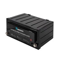
It was a tight fit and the battery sat pretty much flush with the top of the seat base and this limited my choice of swivel. I was a little forced to go down the CTA swivel base route which raised the seat quite a bit. I am ok with the extra seat height, but it is so "rocky"! Here is the problem base that I have, from CTA:
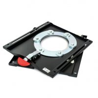
So this time I thought "I'll buy a Roamer which is designed for the job" as I assumed this would provide much more room to accept a broader choice of swivel, but I now note that I am going to encounter the exact same issue and it looks like I shall need to use CTA swivel base again.
Does anyone have any better experience with swivels which don't need that damn big nut, which won't fit due to the height of the battery?

It was a tight fit and the battery sat pretty much flush with the top of the seat base and this limited my choice of swivel. I was a little forced to go down the CTA swivel base route which raised the seat quite a bit. I am ok with the extra seat height, but it is so "rocky"! Here is the problem base that I have, from CTA:

So this time I thought "I'll buy a Roamer which is designed for the job" as I assumed this would provide much more room to accept a broader choice of swivel, but I now note that I am going to encounter the exact same issue and it looks like I shall need to use CTA swivel base again.
Does anyone have any better experience with swivels which don't need that damn big nut, which won't fit due to the height of the battery?
@Soundz - I'm glad your enjoying the ride..... And the threads.Del...very quietly and very slowly your threads are making a little guy's tiny dream edge ever closer. Thank you mate.The detail and the time and effort you put into these threads means even a siimple lad like me is slowly getting his head around ruddy BMVs' BMS's shunts inverters multiple methods of batt charging and fancy LIFEPO4 chemisty stuff that is all above my pay grade.Ha makes me giggle broJees I only have an old 20006 T5 and am now posting on a fancy T6 forum I got set on lithium so so long ago ,it's bonkers.
Anyway Del 2 questions first up are you still using the 200A isolator.......I'm going to need to source one soon and have me heart set on the roamer seatbase so need to be sure on spec.. I'll be using a victron pheonix 12 ve direct inverter so current draw shouldn't be huge....
Second and this is potentially a biggy...............I have two RIB seat swivles so I have to get that Roamer below the seat base......it's a must Del did you remove the earth stud? Can I find some MM's somewhere on the vertical orientation?
Mate I'll leave it there bar an observation.................................. us image makers deal with something called negative space I never realized just how much negative space came into play in a blummin camper build I seem to spend my life trying to scag a few more MM's
take care and again monster thanks
stu
I'm still using a 200A isolator switch ..... But the spec states thats continuous, the surge rate is 500A so I'm happy with that.
No I didn't remove the ground stud... It's still there, it sits about 25mm with the nut ontop. I have nothing connected to it, but may use it in future.
I used the seat base M10 bolt for the main ground.
There is no reason why you couldn't use a grinder to cut off the ground stud...... I did notice on mine that the seat base spacer block was also very close.
And don't forget I have the full carpet fitted, so it's very thick.
For max depth you could cut out the carpet or rubber flooring, that should give you an extra 20mm.
.
Last edited:
Ground off the earth stud. I also used a seat base bolt as the ground.I'm glad your enjoying the ride..... And the threads.
I'm still using a 200A isolator switch ..... But the spec states thats continuous, the surge rate is 500A so I'm happy with that.
No I didn't remove the ground stud... It's still there, it sits about 25mm with the nut ontop. I have nothing connected to it, but may use it in future.
I used the seat base M10 bolt for the main ground.
There is no reason why you couldn't use a grinder to cut off the ground stud...... I did notice on mine that the seat base spacer block was also very close.
And don't forget I have the full carpet fitted, so it's very thick.
For max depth you could cut out the carpet or rubber flooring, that should give you an extra 20mm.
.
I trimmed the seat base spacer blocks slightly.
Also have full cab carpet and this along with the rubber matting I trimmed to get it lower.
I fitted a kiravans swivel base and it’s snug but fits and works fine with the Roamer.
230SB Gen2-v2.
(@RoamerBatteries )
"the next version of the Seatbase battery (due in May 2022) has a slightly tweaked design. We had some issues with the handles on last one so these have now moved to the side. We also found the new T6.1 seatbase is slightly narrower so we’ve shifted the BMS to the front. This has allowed us to reduce width to 280mm but length is now 330mm."
.
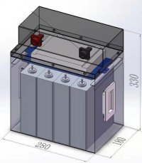
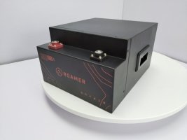
Nice....

.

 www.t6forum.com
.
(@RoamerBatteries )
"the next version of the Seatbase battery (due in May 2022) has a slightly tweaked design. We had some issues with the handles on last one so these have now moved to the side. We also found the new T6.1 seatbase is slightly narrower so we’ve shifted the BMS to the front. This has allowed us to reduce width to 280mm but length is now 330mm."
.


Nice....
.

Roamer Lithium LiFePO4 Seatbase battery
Thanks Steve think 30mm in this case will make a decent difference. I like a challenge when it comes to making things fit.
.
Last edited:
@Linoleum Bonypart which swivle are you using? @Donk ....cheers for the reply.which side drivers or passenger is your battery fitted both? Does anyone by chance know if the T5 seat base is the same dimension as T6 on the vertical side? I ask which side as the drivers in the RIB swivle ( which I really don't want to change) may have extra clearence due to it being made to clear the handbrake when swiveling, well I'm almost certain it does I've had the seats out out so so many times. That said I really want the battery under the passenger side if possible
@Samro ( nice build by the way noted same inverter as what we have in a box if memory serves) that's slightly disconcerting as the Renorgy is 15mm less on the width
@Dellmassive yes loving the ride cheers muchly again someone from the T5 forum linked me to what you were doing, I was always going there but was struggling. I've no full cab matt and have sound deadened and insulated the floor, insulation to edges of seat base so they sit on insulation but not under seats,that will save a few mm. I'm not too worried about grinding off the earth stud as frankly there are so many dotted about my floor.............I strongly suspect I'll make a mock up of the battery (out of wood) now I have the new dimensions from Steve so I can offer everything up.
@Dellmassive seeing that max discharge rate of 500A even if only for 10 seconds was why I asked on the isolator size. I can't see me ever stretching the battery Amps wise only having a 1200 watt inverter plus the 200A mega fuse should protect everything anyway?
I noted your are only using 25mm2 cable ha i've already gone a bit overkill, chose 40mm2 whcih is sort of an unusual size I was recommended 35, for my original plan before I knew about roamer IE a 100AH under each seat so stepped up slightly as I sort of thiink of leccy being like water flowing through pipes and didn't want to constrict anything. Mind my mind set is a bit that way " belt an braces"
Thanks for the help all much appreciated
stu
edited to add the @
Last edited by a moderator:
@Soundz add the @ symbol before the names to auto tag them in ie do @DellmassiveLinoleum bonepart which swivle are you using? Donk.....cheers for the reply.which side drivers or passenger is your battery fitted both? Does anyone by chance know if the T5 seat base is the same dimension as T6 on the vertical side? I ask which side as the drivers in the RIB swivle ( which I really don't want to change) may have extra clearence due to it being made to clear the handbrake when swiveling, well I'm almost certain it does I've had the seats out out so so many times. That said I really want the battery under the passenger side if possible
Samro ( nice build by the way noted same inverter as what we have in a box if memory serves) that's slightly disconcerting as the Renorgy is 15mm less on the width
Del yes loving the ride cheers muchly again someone from the T5 forum linked me to what you were doing, I was always going there but was struggling. I've no full cab matt and have sound deadened and insulated the floor, insulation to edges of seat base so they sit on insulation but not under seats,that will save a few mm. I'm not too worried about grinding off the earth stud as frankly there are so many dotted about my floor.............I strongly suspect I'll make a mock up of the battery (out of wood) now I have the new dimensions from Steve so I can offer everything up.
Del seeing that max discharge rate of 500A even if only for 10 seconds was why I asked on the isolator size. I can't see me ever stretching the battery Amps wise only having a 1200 watt inverter plus the 200A mega fuse should protect everything anyway?
I noted your are only using 25mm2 cable ha i've already gone a bit overkill, chose 40mm2 whcih is sort of an unusual size I was recommended 35, for my original plan before I knew about roamer IE a 100AH under each seat so stepped up slightly as I sort of thiink of leccy being like water flowing through pipes and didn't want to constrict anything. Mind my mind set is a bit that way " belt an braces"
Thanks for the help all much appreciated
stu
@Dellmassive Gotcha Del.......TBF ....I thought the like button would send an alert and having posted on the thread folk would be notified of replies, but not all fora work the same Funny I've just done exactly just that with Steve ( Roamer) trying to pin down exacts of SB battery size
cheers for the heads up i'm not great with PC's
cheers for the heads up
The van has been layed up for three weeks...
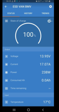
The LB has been running a BM2 battery monitor, an AMT12-2 starter battery trickle charger and a Victron Cerbo GX monitor.
The main draw is 400mA continuous..
It's interesting to see the drift from the Battery BMS data and the Victron shunt.
The battery BMS shows 92%.
But the Victron shunt shows, 46%
This is because the battery BMS has difficulty logging loads under 500mA
..so the true reading is 46%
This is just an example of why people ask me why I have the Victron shunt as well as the battery internal BMS.
This is not a fault or an issue, most BMS are the same, some are better than others.
The Roamer is actually very good in reading low current loads.... Much better than say the Poweroad that has problems reading under 1A (1000mA)...... This can lead to a drifting SOC reading.
The fix though Is easy. . . .
Just charge the battery to 100% this will reset the BMS back to 100% SoC and start the cycle again.
Happy days.
...
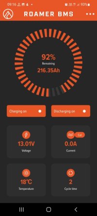
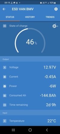


just the update on the above . . . .
( the van being left for 3 weeks with a low sub 500mA load switched on - which caused a SoC drift from the battery BMS and Shunt data)
The BMS drift showed 46% and 92%.
( FYI - this can happen on all large lithium batterys with very low loads)
after a couple of days charging via the Renogy DC50s the Roamer is again fully charged.
++
both BMS and shunt are now showing 100% and we are back to normal operation.
this is only a temporary effect and you can see it took 3weeks to drift, and two days to correct its self.
this wont be an issue over long weekends or or even weeks if the van is driven causing a dc-dc charger to recharge & reset anyway.
you will only notice this on extended stays with a very low consumption - ie van parked up alone in storage, with no charge source.
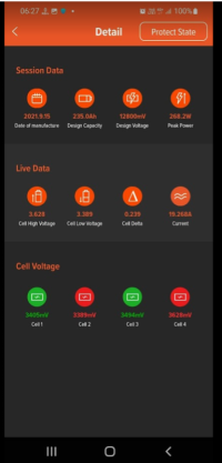
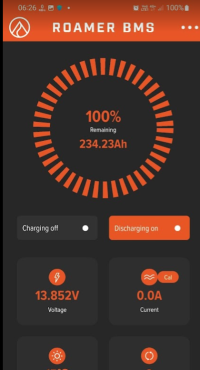
+++
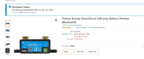
I've had a few people asking me what im using for the stand alone shunt ( That i run alongside the lithium batterys):
im using the Victron Smart shunt:
this is Bluetooth so connects to the victron app on your phone.
+++
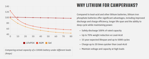
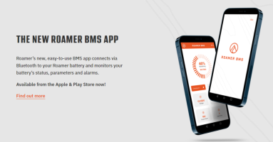
for the battery, check out ROAMER:

 roamer.com


( the van being left for 3 weeks with a low sub 500mA load switched on - which caused a SoC drift from the battery BMS and Shunt data)
The BMS drift showed 46% and 92%.
( FYI - this can happen on all large lithium batterys with very low loads)
after a couple of days charging via the Renogy DC50s the Roamer is again fully charged.
++
both BMS and shunt are now showing 100% and we are back to normal operation.
this is only a temporary effect and you can see it took 3weeks to drift, and two days to correct its self.
this wont be an issue over long weekends or or even weeks if the van is driven causing a dc-dc charger to recharge & reset anyway.
you will only notice this on extended stays with a very low consumption - ie van parked up alone in storage, with no charge source.


+++
I've had a few people asking me what im using for the stand alone shunt ( That i run alongside the lithium batterys):
im using the Victron Smart shunt:
this is Bluetooth so connects to the victron app on your phone.

+++
for the battery, check out ROAMER:

Roamer - Premium LiFePO4 lithium Leisure Batteries
Roamer SMART4, XTREME and HOME - the next generation in 12v 24V and 48V LiFePO4 lithium leisure batteries for campervans, motorhomes and boats. From 100Ah to 460Ah capacity with Bluetooth BMS, Victron GX integration, Active Balancing and low temperature charge protection. 5 Star UK support, 10...


Last edited:
@Dellmassive .......Dell, pane 73 you show a pic of a fuse block in the "flir" temperature check piccies...........which one is it and where in the SB is it located please..........
Cheers for the above info yup have smart shunt to run alongside the roamer BMS.....been re reading the thread whilst trying to get me head around where to fit everything under two single T5 SB's and musing ....I noticed cell 4 is again at a higher voltage in the latest installment ....as it was when you saw the COV readings due to the renorgy beiing set a gnats high at 14.4.V.which you then changed to roamer's spec of 14.2. and all became well......
Mate is that normal so see a slight difference in the cells and one in particular is often higher. and nowt to worry on...................and what is the significance of the cells being illustrated in red or green in the roamer app?
many thanks
stu
Similar threads
- Replies
- 48
- Views
- 4K
- Replies
- 102
- Views
- 11K
- Replies
- 13
- Views
- 2K
- Replies
- 3
- Views
- 2K

