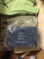
Valence U27-12XP Lifepo4 Lithium Battery -- How We Done It --

@ched
@andys

I have no hands-on experience of the the Victron Orion chargers but I have had a look at the full manual.

Please note that there is a difference between 'Remote on/off' and 'Engine detection override'.
  • Remote on/off allows you to disable or enable the charger. When the charger is enabled, it uses the 'Engine on detection algorithm' to determine when to charge the battery.
  • Engine detection override simply turns the charger on and off with a control signal (e.g. switched 12V from ignition). The 'Engine on detection algorithm' is ignored.
I would recommend you use 'Remote on/off' to control when the charger is enabled. This allows you to disable the charger in low temperatures. The key advantage is that you will not run your engine battery down if you simply leave the ignition on! This is because the engine still has to be running before charging is enabled.

You can use option (b) to switch from +12V [connect to H only] or (d) to switch to ground [connect to L only]. A relay could also be used as the switch if that works better for you.

View attachment 96500
'Figure 3: Remote on/off connections' from page 9 of the full manual.

NOTE: If you connect both L and H together to +12V, you will disable the 'Engine on detection algorithm', i.e. place the charger into 'Engine detection override' mode.

Hope this helps.
Thanks yes I read the manual before fitting. I've done as I put above, stuck with using the remote turn on via the relay on my thermostat and broken it with a relay fed by an ignition live which disconnects the remote when the ignition is off. I've disabled the engine detection via bluetooth and reduced the voltage cutoff to 11.9v. Effectively configuration a) above, with two switches (the ignition controlled relay and the temperature controlled relay) in series.This seems to work fine in practice and gives it the functionality I had from my Ctek. I'm not concerned about draining the battery by leaving the ignition on, I've never done it before and haven't lost my marbles yet :D

I also fitted the Victron 15A mains charger in place of the existing Westfalia unit to compete the trio of lithium capable chargers. It's a fair bit lighter and smaller than the outgoing one and I was able to secure it to the ceiling of the cupboard it was in rather than the side wall, which has given a bit more usable space inside. Shame it's not also temperature controlled, I suppose I could rig up another of the temperature controlled relays I've already used but I don't think I will.

This low temperature charging limitation is certainly more of a restriction than I thought it would be, especially if it takes more than 20 mins of driving before charging can commence. I think heating mats may be a future solution, it would require power from the battery but if charging could start sooner, the 30A input would quickly replace that and would be irrelevant if connected to the mains.

Anyway, my Valence setup is now done, just as we enter weather cold enough that it can't be charged.
 
I installed my Valence battery in 2019. At the time I could not find the Valence software anywhere. I assumed that because the datasheet said that balancing happens on the top end of charging that I did not have to worry about balancing and the BMS would do that. On the 1st charge from solar after installation I was idly sitting in my van enjoying a brew while watching the voltage. At around 14V the voltage started jumping around a bit, there were no clouds going over and the amps from solar were not changing much. I assumed at the time that this was balancing in action and some banks were being discharged.

Reading this thread it seems that it's been proven that BMS sleeps unless 5v and rs485 are present. I have ordered a USB rs485 adapter and installed the software ready in a VM on my laptop. It will be interesting to see how out of balance the banks are after two years - What I am wondering is what SOC should I be at when I 1st plug in the software so that I am best able to see any imbalances? I am thinking maybe something below 13.8V - check spread. Then charge up and observe again? rinse & repeat a few charge cycles later to determine how often I need to take my laptop to the garage?

I had considered removing the BMS completely and replacing it with one with bluetooth for monitoring, I have some experience of these from escooters/ebikes. These have over/under voltage & over current protection which the valence BMS does not, its just a cell balancer with monitoring. Since finding this informative thread I will just get a cable and use the software @Dellmassive kindly provided.
 
It will be interesting to see how out of balance the banks are after two years

That will be interesting @scote. Please report back when you’ve hooked your battery up to the Valence software.

It’s kinda reassuring that you’ve been running yours since 2019 without cell balancing and you’ve not experienced any ill effects!
 
just been in contact with the seller . . .

due to the high demand of these Lifepo4 batteries.

They are releasing another 20 units for sale. . .


so if your thinking of Lithium upgrade in the future you can grab one now at a great price =]


its looking with most have under 50 charge/discharge cycles . . and over 93% capacity


*-*-*---


View attachment 85719
For Sale - Valence U27-12XP Series 12V 138ah Lifepo4 Battery
Valence U27-12XP Series 12V 138ah Lifepo4 Battery ok people, the seller has said we can do a group buy. There are 10-20 batteries available, they are listed else where, so its first come first served. - once they are gone . . . there gone. They are £305 each via cash or BACS and to be...
www.t6forum.com
www.t6forum.com


**


1600273838510.png
Hello mate, do you know if there are any of these batteries currently available from your supplier?

Cheers,
Darren
 
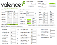
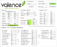
I connected my U27-12XP rev 1 to the app after two years installed in my van. It is an older model, black instead of green and with a different rs485 connector round 5pin M12. It was purchased from the same vendor in Bristol that is in an ebay screenshot earlier in the thread (davidsinpelo). I did not leave the laptop connected, plug in to take measurements and screen shot then disconnect:

The battery was 13.1V when I connected and the groups were within 5mV already. I left it on charge overnight 7A charger - charged to 14.4V then float at 13.8V the cell groups got out of balance by about 90mV. Disconnect charger, leave for two hours, then plug in laptop again. Cells where balanced to within 5mV, voltage dropped to 13.5V. This behavior appears to be different to the newer green rev 2 batteries.

My BMS has working current measurement, so I took the opportunity to see what amperage I got through my Victron Cyrix CT VSR (Voltage sensitive Split Charge) it was about 25A at idle which is great, the datasheet advises a max of 20A, I would only use this for emergency use so I usually have the fuse removed for this circuit as I dont want my alternator pumping 14.2V into it every time I drive (I don't have smart alternator). The battery is usually charged via 300W solar panel, van is garaged so it only sees light when I go out.

BMS does not log watt hours, the charge cycle measurement is a bit funky - it went from 616 charge cycles to 629 charge cycles from this one charge

Temperature sensors appear to be in hundredths of a degree C - its was about 3C when I started yesterday and the post charge temperature was 5C which is about what ambient temp was today.

If you do not run the app with Administrator privilege you get an extra tab which can force balancing. It may be possible to sort out the file permissions in the valance Program folder after starting the app, I think you get the extra tab because it cant access the config file, maybe changing the access rights on that folder/file after starting the app could get is to connect and run which is does not currently - or even just copy the exe and config file to desktop and run it from there. I did make the change to the config file mentioned earlier in this thread to enable the calibration tab. I did not attempt to do anything there though.

Hopefully this may be of help to anyone that picks up one of the older Valence batteries. My battery still performs very well despite its age, the voltage does not go down much at night with phones charging, lights, fridge etc. It charges up rapidly when the sun rises on the morning, lead acid would take longer, so if its intermittent clouds you can take advantage of the sun when it appears with lifepo4 due to its high acceptance of current.

Before charging Battery info tab:
1.png

Before Charging Event log tab:
2.png

After charging:
4.png

Diagnostic cable I made with rs485 USB adapter - the connector is known as 5pin M12 - pin2=5v, pin3=gnd, pin4=rs485_A, pin5=rs485_B

IMG_20210117_154446.jpg
 
I see some Valence LiFePo4 130Ah batteries have appeared on eBay if anyone is interested. No pictures or type number so will need checking. 10 available apparently. In Bristol. Valence LiFePo4 130Ah battery | eBay
Doesn’t state if Rev 1 or Rev 2 but if you have the software and want to visit it looks like it’s possible to do some checks beforehand.
I paid £315 for my Rev 2 to build a power pack for my canoe. Total spend so far is £1020 and I still have some fine tuning to do!!! It doesn’t stop with the battery.
 
The last piece of the Lithium jigsaw arrived today. Might be able to get the seat back in!! Good job I've not been going anywhere. Mind you I'm still waiting for the App.Ablemail.jpg
 
There's something amiss with my charging setup, went to work in it today so I could pick up my MOT cert after having a tyre replaced and noticed that after a couple of weeks of virtually no use, the charge status monitor was reading 51%. After driving for a while I stuck my phone in a holder and fired up the Victron app to see that the the Orion 30A DCDC charger was reporting it had gone into float, but flicking to the 100/20 MPPT readout showed that it was getting 60/70W from the solar (nicest weather for ages today) and was reading Bulk charging(?). When I got back it was reading 63% and I plugged the EHU in so it could charge from the Victron 15A mains charger. Came back to it a short time later to find it was reading 71% (92AH) and the charger had gone into storage mode. This all seems a bit weird... or does it? First time I've really had chance to see how this setup is getting on.
 
Well done guys im so impressed with the effort and progress you have all made with these batterys and this thread.

some how i missed about 5-pages of content as the notification for this thread for me went a bit janky for me (about oct-dec) . . . . i re-read the whole thread last night and fully caught up.

Great work from all of you. - A pat on the back, buy yourselves a beer. =]


@Hickey - install is looking great
@Dilbert - great input (nice PP work)(great install)
@Lowlec - awesome technical input
@ched, @DXX, - great computer work
@Brennanpj - love the battery box
@Sjbso2000 - well done
@andys - nice work, is the charging working correctly now?
@Jollyvan - well done for taking this project on, its looking great
@caerfilthy - well done
@drew_greenday - well done
@scote - good to the V1 battery is still kicking
 
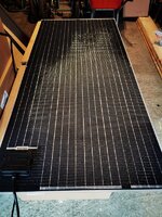
My solar and controller turned up yesterday so thought I'd connect them up to see what it pulls on a rainy day a massive 10W! ️️IMG_20210206_125835.jpgIMG_20210206_130906.jpgIMG_20210206_131020.jpg
 
Go team victron . .

what the solar panel?

got any screen shots from the Victron APP?


edit: nice van blanket . . . . whats the details on that?


Cover was a maypole 1 I think its nearly 5 years old so lasted well but getting ready for a new 1 soon.

Sunstore 195w semi flexible
Screenshot_20210206_132732_com.victronenergy.victronconnect.jpg
IMG_20210206_133055.jpg
 
As promised, here is the diagram that shows the configuration of the chargers, low voltage battery protection and low temperature charge control.

View attachment 87867

  • The Smart battery protect is configured (with the Victron Connect app is easiest) to provide low voltage disconnect of the load if the battery voltage goes below 11.5V.
  • The MPPT charge controller has built in low temperature cut-off that you can configure with the Victron Connect app. This is set to 5 deg C. (The MPPT receives its temperature data from the BMV via Victron’s VE.Smart network connection).
  • The Battery to Battery (B2B) charger is configured to require an Ignition +12V or engine run +12V to enable it to charge. For the Sterling BB1230 this requires it to be operated in ‘Mode 2’ or ‘Mode 3’. This Ignition/engine run signal is passed through RELAY 1.
  • The Mains hook up charger has its output going through RELAY 2.
  • The relays are controlled by the BMV-712 and this must also have the optional Temperature Sensor fitted to the positive terminal of the battery.
The relays are standard change over relays rated at 40A. The ignition/engine run signal relay does not need to be such a high current relay but this type of relay provides for easy termination of the connectors (and I had plenty of them!).

I chose to discreetly switch only the affected chargers, rather than isolate all chargers with one large relay, because some chargers need to ‘see’ the load battery first to operate correctly.

The relays are energised by the internal contacts in the BMV-712. The contacts are configurable via the BMV display or the Victron Connect app. The latter being much easier.
  • A fused positive feed* goes to the BMV display contact Common (COM) connection. The BMV Normally Open (NO) connection then goes to both relay coils (86).
  • The other relay coil connection (85) of both relays connects to ground (0V).
  • The relays use the normally closed contacts (87a) and common (30) to do the switching.
  • Under normal operation the relay is not energised and the normally closed contacts are made.
  • If low temperature is detected, the relays are energised and the normally closed contacts go open and remove the feeds. This then means [1] the Ignition +12V/engine run signal no longer reaches the B2B charger so it shuts down, and [2] the output from the Mains changer is disconnected from the battery.
*[Note: I took the +12V feed for the relays from the battery side of the low voltage Battery Protect. This was to ensure the low temperature charge protection would work in the event of the battery being below 11.5V at the same time. This obviously risks the relays discharging the battery below 11.5V as this current draw is unprotected. But the circumstances are hopefully very unlikely!].


This is the Victron Connect app BMV ‘Relay’ configuration menu. You will see I have also configured a high temperature protection as well as low temperature. I also set a minimum relay closed time of 1 minute to stop any rapid on-off-on switching.
View attachment 87869


This is the BMV temperature setting sub menu where you can configure the ‘Set value’ to activate the relays and the ‘Clear value’ deactivates the relays.
View attachment 87870


Hope this helps. Let me know if you have any questions.

D.
Great information and setup @Dilbert . I can see how the LTD is set up for the MPPT solar controller. However I cant work out how the battery is prevented from bing charged when the engine is switched on and the battery is say below 5C? Thanks
 
I cant work out how the battery is prevented from bing charged when the engine is switched on and the battery is say below 5C?

The BMV is programmed using the app to control it's internal relay to that it changes state when the temperature is below 5 deg C. The internal relay provides power to the external relays; Relay 1 and Relay 2.

The Battery to Battery (B2B) charger is configured to require an Ignition +12V or engine run +12V to enable it to charge. (For the Sterling BB1230 this requires it to be operated in ‘Mode 2’ or ‘Mode 3’). This Ignition/engine run signal is passed through RELAY 1 - mauve wire in the diagram. If the temperature is below 5 deg C, the B2B charger will not receive the enable signal so cannot turn on.

Please note I have posted 2 versions of the diagram - the one you have quoted is the non-fail safe version. A later post shows the Fail Safe version. The logic of the relays is reversed between the 2 versions. Hence I have tried to keep this description generic.

Hope this helps but please shout if you need more information. :thumbsup:

[EDIT] If you tell me which of the 2 versions you wish to use, I can provide a more detailed explanation if required.
Thanks. I will have a look again at the 2 versions. However I was planning on using a Victron B2B charger and I don’t think they have the remote switch on wire.
 
Back
Top